the Creative Commons Attribution 4.0 License.
the Creative Commons Attribution 4.0 License.
 | 14 Oct 2024
History of the Potsdam, Seddin and Niemegk geomagnetic observatories – Part 3: Niemegk
Hans-Joachim Linthe
The measurement series of the three geomagnetic observatories Potsdam, Seddin and Niemegk spans more than 130 years, starting in 1890. It is one of the longest, almost uninterrupted series of recordings of the Earth's magnetic field. Data users frequently emphasise the high quality of the data and their significance for geomagnetic base research. Very well known outstanding geomagnetism scientists, such as Max Eschenhagen, Adolf Schmidt, Julius Bartels, Gerhard Fanselau and Horst Wiese, directed the three observatories in historical sequence.
This paper describes the history of the Niemegk Adolf Schmidt Observatory, which was started in 1932 and is currently still in operation.


The Potsdam Prussian Meteorological Magnetic Observatory operated two magnetic observatories: Potsdam on the Telegrafenberg near the town of Potsdam, which was in operation from 1890–1928, and Seddin near the village of Seddin, which was in operation from 1907–1932. Anthropogenic noise from DC-powered railway traction vehicles, which were operated in small distances, caused the termination of both the magnetic observatories (Best et al., 1991, 1992; Linthe, 2023a, b). It was necessary to find a suitable location for a new observatory that could allow for undisturbed long-term operation.
Adolf Schmidt was successful in doing this job. The mayor of the town of Niemegk offered excellent conditions for the new observatory. The construction of the observatory buildings took place under extreme time pressure – Potsdam and Seddin had already been disturbed by the DC-powered railway traction vehicles.
The next problems occurred by upwelling groundwater in the variation house, which caused comprehensive construction repairs. The end of World War II in 1945 caused building and instrument damage and – most serious – the lost of instruments. The observatory personnel restarted the observations under extremely difficult conditions, but they could not prevent a data gap of 9 months.
The following decades were years of precise observations, successful scientific research, fruitful international collaboration and excellent instrument construction. German reunification in 1990 implicated dramatic changes for the observatory. The number of employees decreased extremely, but the conditions of the operation of the observatory improved greatly. Modern instruments were purchased, and the access of up-to-date IT hard- and software made the complete digitalisation of the observatory possible.
The Kp Index Service of the International Service of Geomagnetic Indices was taken over from Göttingen University in 1997. Actually it was a return home – the K index was invented on the basis of Niemegk recordings in 1939. Even scientific conferences were performed at the observatory. Two employees of the observatory were awarded a long-service medal by the International Association of Geomagnetism and Aeronomy (IAGA).
In the beginning of the Potsdam–Seddin–Niemegk data series, from 1890–1932, the observatories belonged to the Potsdam Meteorological Magnetic Observatory. From 1933–1991, a period of several affiliation changes followed. From 1992 onward, a period of constant affiliation to the GeoForschungsZentrum Potsdam – now termed Helmholtz Centre Potsdam, GFZ German Research Centre for Geosciences – followed.
The most important fact about the observatories is the unchanged magnetically clean observing conditions from the beginning until today; therefore, Adolf Schmidt selected an excellent place for the observatory. Furthermore, the administration of the town of Niemegk accepted the agreement stating the conditions of an undisturbed operation over the complete operation time – almost 100 years.
The famous Adolf Schmidt (1860–1944), director of the magnetic observatories from 1902–1928, tackled the task of finding a suitable place for a new observatory. At first he considered locations near the villages of Raben and Rädigke in the Hoher Fläming hills (Bock, 1950). But the power supply and building heating were a problem at that time at these locations. But due to a favourable circumstance, Adolf Schmidt found a suitable location. Paul Temming (1884–1953), mayor of the small town of Niemegk from 1917–1937, obtained knowledge of Adolf Schmidt's intension to establish a magnetic observatory in the region of Hoher Fläming by chance. He expected development opportunities for Niemegk with such a facility in the town. He made Adolf Schmidt aware of his idea. Schmidt presented his expectations of the location and the conditions of the undisturbed operation of the observatory. The negotiations of both the authorities came to the successful result of establishing the new observatory at a distance of 1000 m from the town boundary at the edge of a forest (Nippoldt, 1929). On Adolf Schmidt's request, in a contract, the town of Niemegk and the observatory agreed to ensure the undisturbed operation of the observations. The town of Niemegk committed to abstain from DC facilities and to accept a protection circle of 500 m radius around the observatory, in which any constructions should be allowed only in the case of the permission by the observatory. Figure 1 shows this contract.
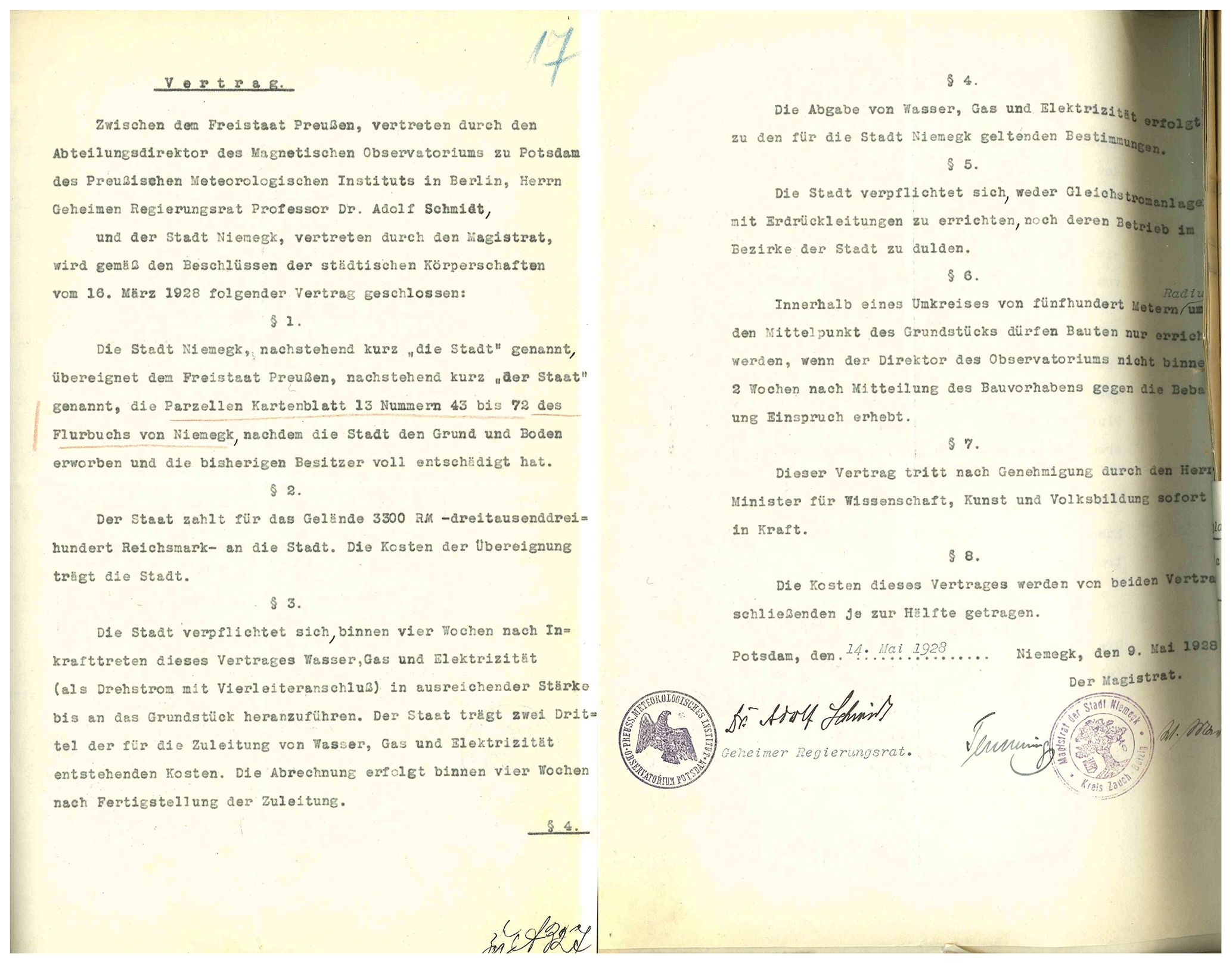
Figure 1Contract between the Free State of Prussia, represented by Adolf Schmidt, and the magistrate of the town of Niemegk, represented by the mayor Paul Temming, on the conditions for the undisturbed operation of the new observatory. Source: Helmholtz Centre Potsdam – GFZ.
The town of Niemegk bought the properties from private owners and sold it to the observatory for half the price. Furthermore, the town constructed a gas and water pipeline and electrical power supply connection to the observatory, bearing one-third of the expenses (Bock, 1950).
It was intended to start and finish the construction of the new observatory in 1927 to enable the parallel operation of Seddin and Niemegk over a suitable time period. The Deutsche Reichsbahn-Gesellschaft, owner of the Berlin suburban railway, announced the launch of electrical operation of the trains at the beginning of 1929. In fact it had started already on 11 June 1928. But the construction of the Niemegk Observatory only started in 1929 and only started being functional in the course of 1931. The parallel operation of Seddin and Niemegk was only possible during the time period of almost 1 year, but the Seddin observations had already been disturbed by the leakage currents of the electrical trains (Linthe, 2023b).
Adolf Schmidt continued to accompany the activities even after retiring on 1 October 1929. He actively influenced the construction plans of the buildings and their locations. The Deutsche Reichsbahn-Gesellschaft, the operator of the DC-powered Berlin suburban railway, as the originator of the movement of the observatory from Potsdam and Seddin to Niemegk, contributed a significant fee to the costs of the new observatory on the basis of a contract – as a result of Schmidt's successful negotiations (Nippoldt, 1930; Best, 1997).
The construction activities of the observatory started on 3 May 1929 (Nippoldt, 1931b). On 1 April 1930, the Prussian Minister for Science, Art and Education granted the new observatory the name “Adolf-Schmidt-Observatorium für Erdmagnetismus Niemegk”. Figure 2 shows the document. On 23 July 1930, Adolf Schmidt's 70th birthday, the observatory was officially opened (Nippoldt, 1931a). Figure 3 shows the first page of the observatory guest book with Adolf Schmidt's inscription. He wrote his motto “To be always excellent and to distinguish from others” in Greek and old-style German. A total of 46 invited persons participated in the opening ceremony. Figure 4 shows the inscriptions of all of them depicted in the guest book .
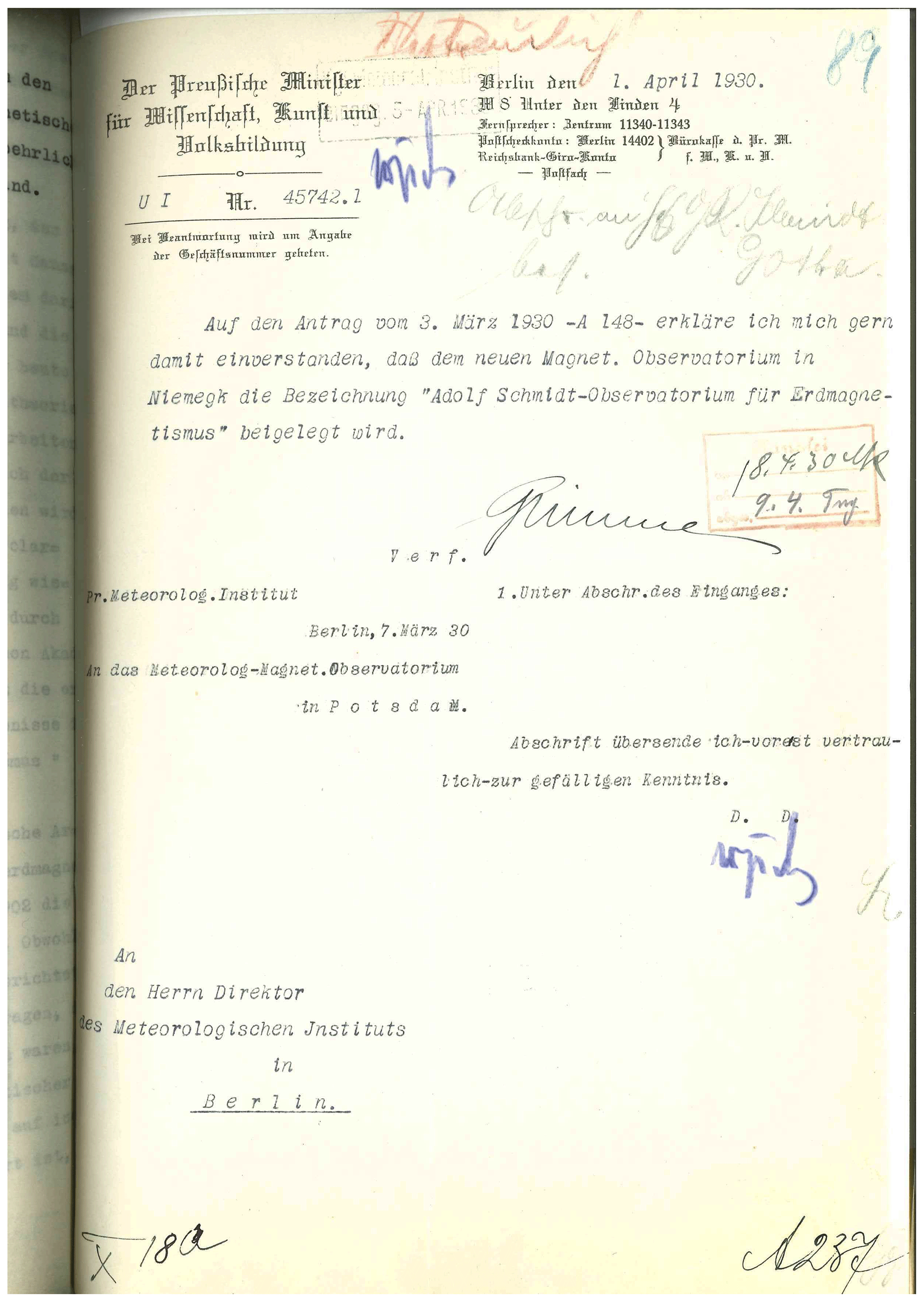
Figure 2Document from the Prussian Ministry for Science, Art and Education from 1 April 1928 attaching the name “Adolf-Schmidt Observatorium für Erdmagnetismus Niemegk” to the new observatory (Niemegk Adolf Schmidt Geomagnetic Observatory). Source: Helmholtz Centre Potsdam – GFZ.
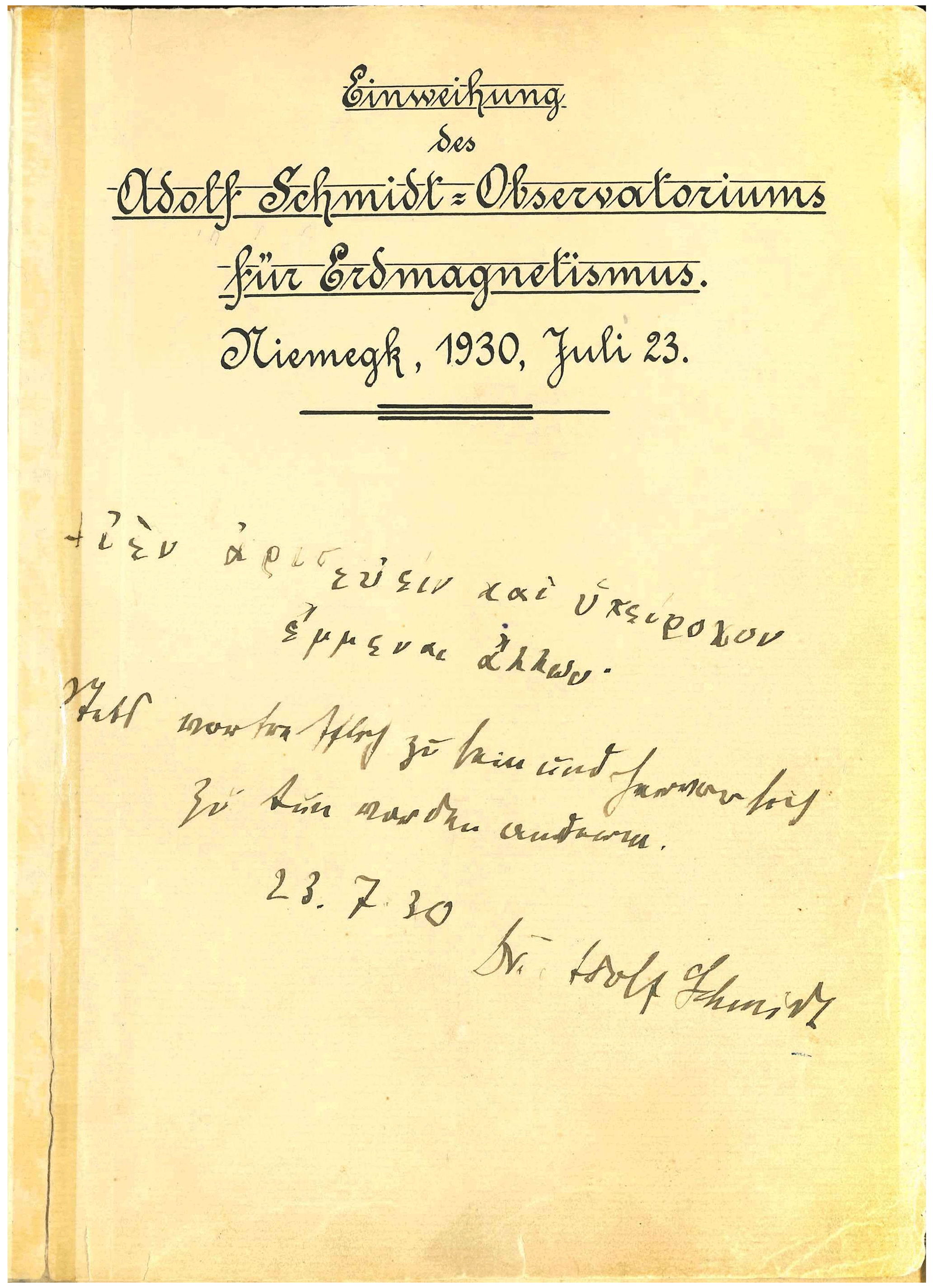
Figure 3First page of the observatory guest book with Adolf Schmidt's inscription. Source: Helmholtz Centre Potsdam – GFZ.
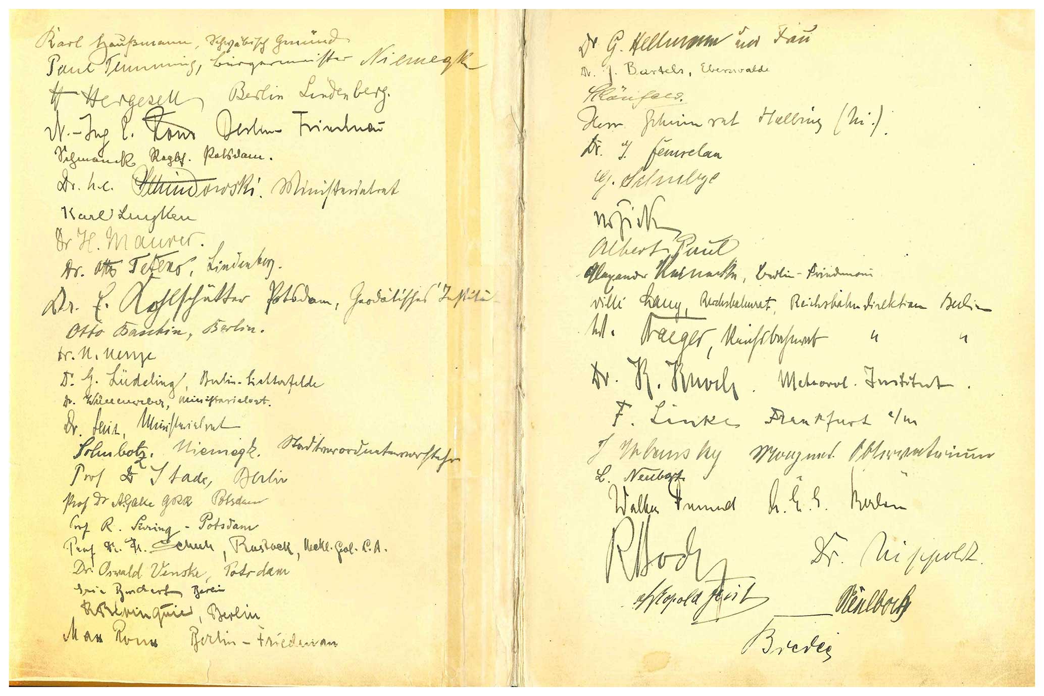
Figure 4Inscriptions of the participants of the observatory opening ceremony. Source: Helmholtz Centre Potsdam – GFZ.
After the building construction was completed in 1931, the instruments were installed and adjusted by Richard Bock (1899–1961). The operation of Seddin Observatory was continued until 9 May 1932. On 1 January 1932, the observations started officially at the Niemegk Adolf Schmidt Observatory (Bock, 1950).
2.1 Niemegk Observatory buildings
Figure 5 shows the ground plan of the new observatory compound of a size of 3.5 ha (Bock, 1939). The solid-clinker-constructed apartment and service building (later called the main building) contains two apartments, some offices, two guest rooms, the necessary power supply equipment, a workshop and a central heating system. In the solid clinker-constructed storage house were also a garage, a laundry and storage rooms. Figure 6 shows a photo of both the buildings.
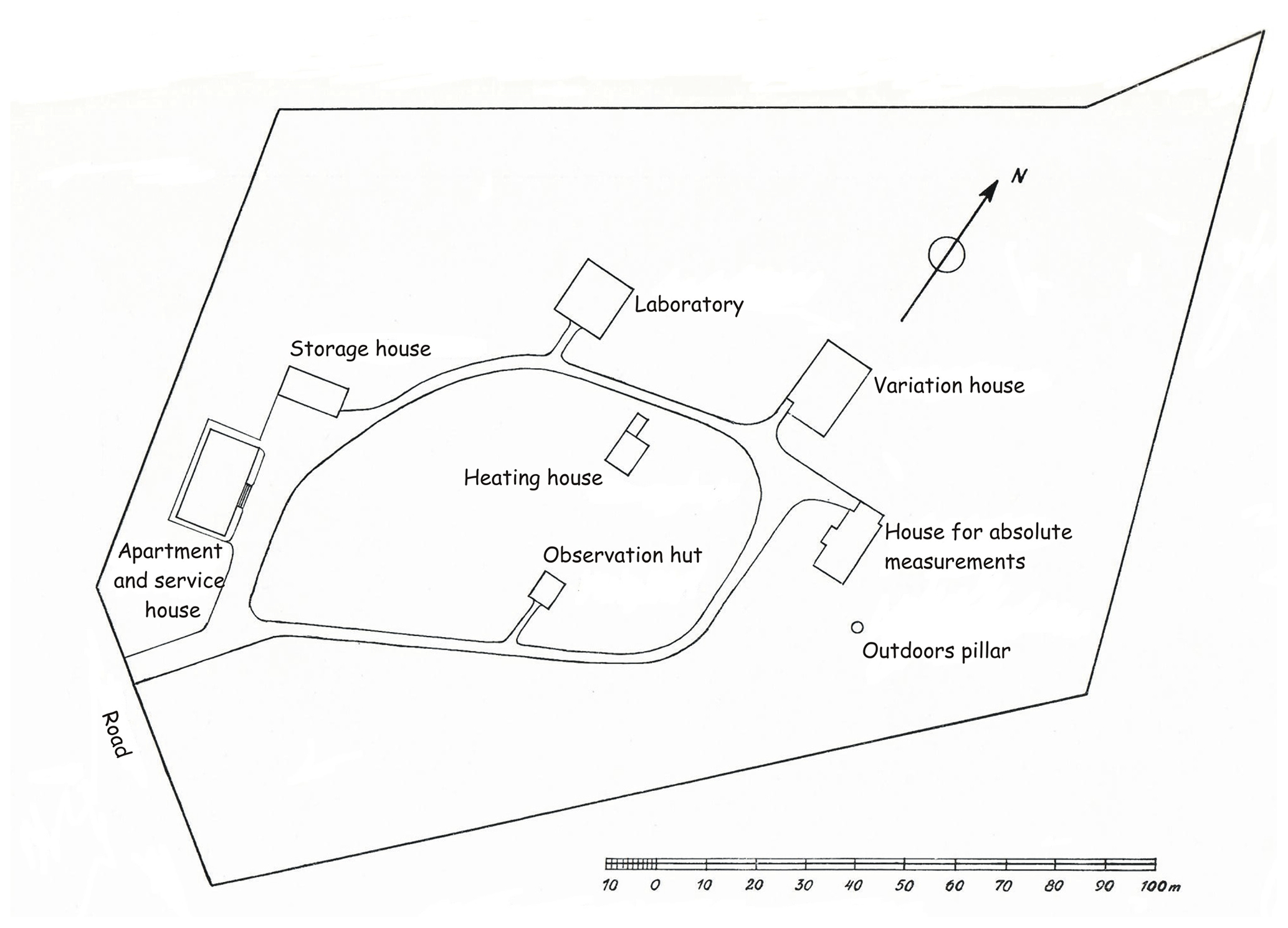
Figure 5Compound plan of the Niemegk Adolf Schmidt Observatory. Source: Bock (1939).
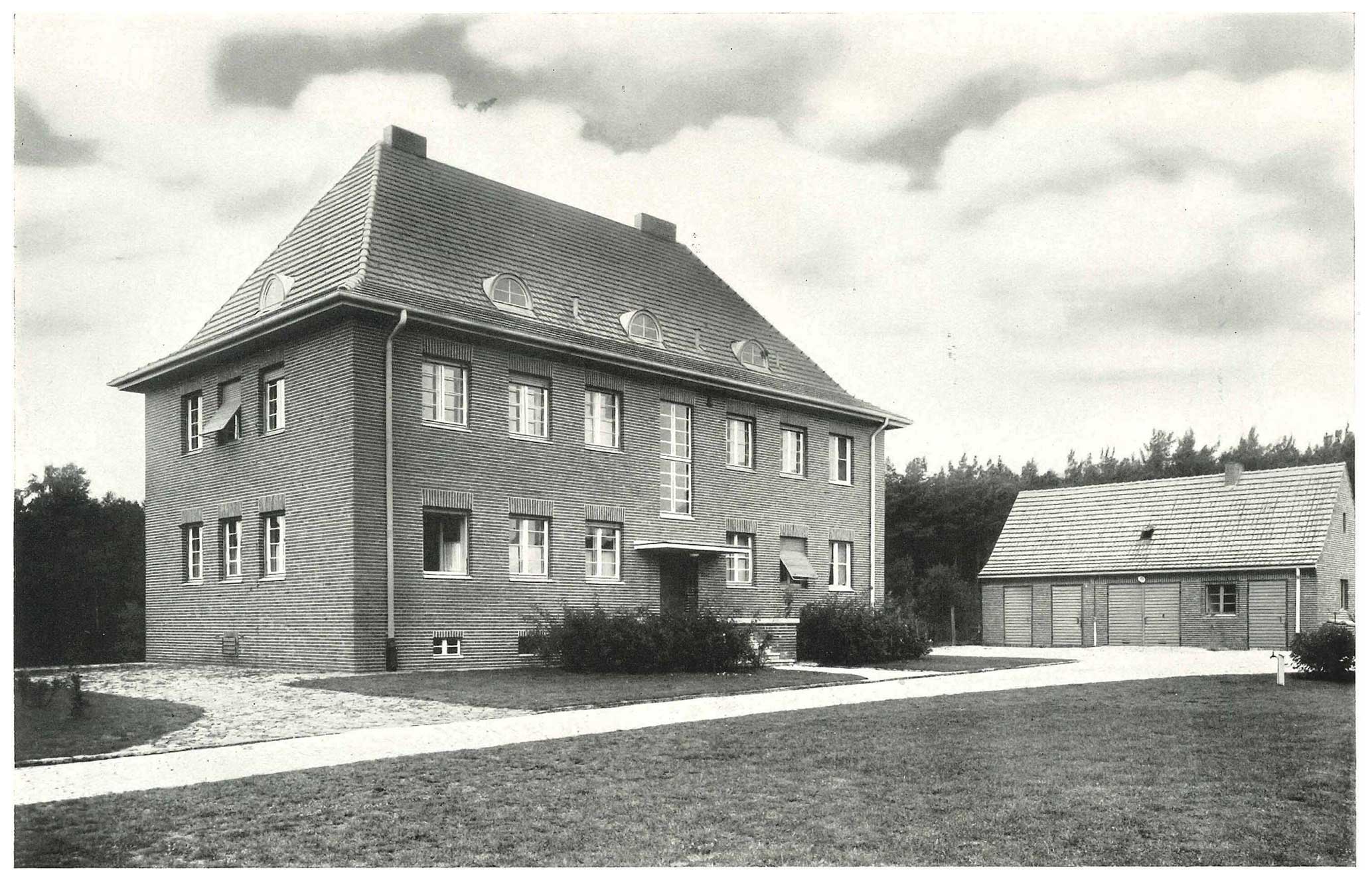
Figure 6Photo of the apartment and service house (left) and the storage house (right). Source: Bock (1939).
The house for absolute measurements (later called absolute house) and the variation house are made of wood on a concrete foundation. The sand, cement and further additives, used for the concrete, were carefully investigated to check if they were free of any magnetic influence on the observations. Any fitting assemblies are made from brass, and the nails are copper ones. The pillars for the instruments are also made from concrete and are resting in groups together (variation house) or all together (absolute house) on a concrete foundation that is 50 cm thick. An outdoor pillar is located eastward of the absolute house.
The absolute house (see a photo in Fig. 7 and the ground plan in Fig. 9) consists of a crawl space below the Earth's surface and the measurement room at the ground floor with another crawl loft for thermal insulation. A total of 16 pillars are available for the vibration-free placement of instruments (14 in the main room and another 2 in a special annex chamber at the west wall). The church tower (viewable in Fig. 12) and the water tower of the town of Niemegk at a distance of about 1000 m, visible from some of the pillars, serve as azimuth marks. Before the wooden construction of the house was started, astronomical measurements to determine the azimuth values of a number of inside pillars and the outside one with respect to the azimuth marks were made (Nippoldt, 1930).
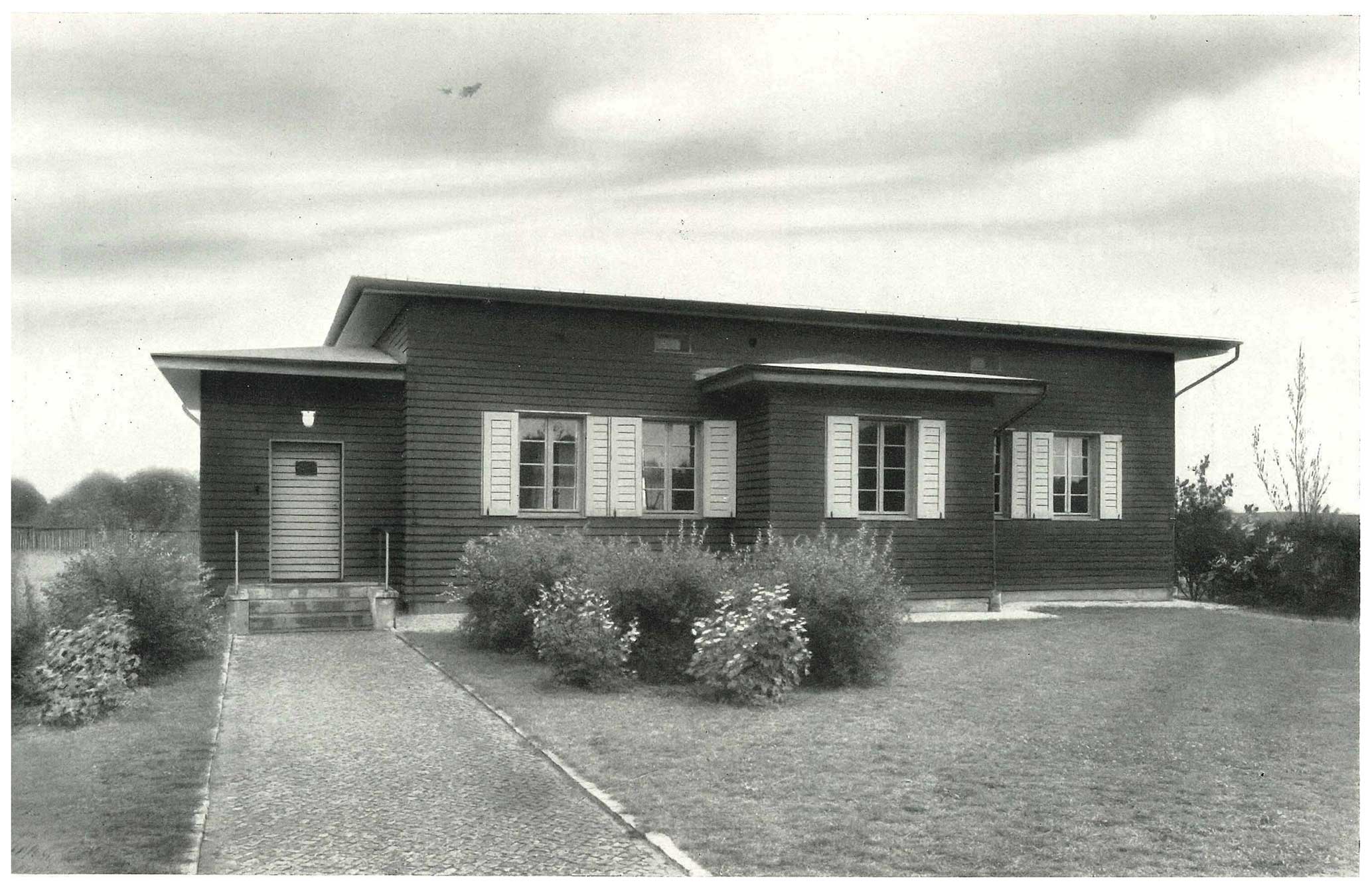
Figure 7Photo of the absolute house. Source: Bock (1939).
In 1957, inner walls with thermal insulation and thermoelectric-controlled heating were added to the absolute house to ensure a constant temperature for the absolute measurements (Wiese, 1960). All this was removed in 2003 and 2004 in connection with the basic renovation of the building. Since the invention of the new set of absolute measurement instruments from 1992–1996, a strict constant temperature during the absolute measurement set has not been necessary any more.
The variation house (see a photo in Fig. 8 and the ground plan in Fig. 10) was partly sunk below the Earth's surface to avoid a thermal influence on the instruments as far as possible. Around the instrument rooms, there is an insulation corridor for further thermal protection. Three rooms, named following their geographic directions – south, north-east and north-west – are intended to be used for the instruments. A service corridor in the centre allows for access to the recording equipment of both of the northern rooms and the south room. The wooden loft with a roof over the whole concrete basement is further intended to avoid thermal influence on the instruments. A crawl space below the wooden floor of the instrument rooms and the service corridor allows for the placement of cables.

Figure 8Photo of the variation house. Source: Bock (1939).
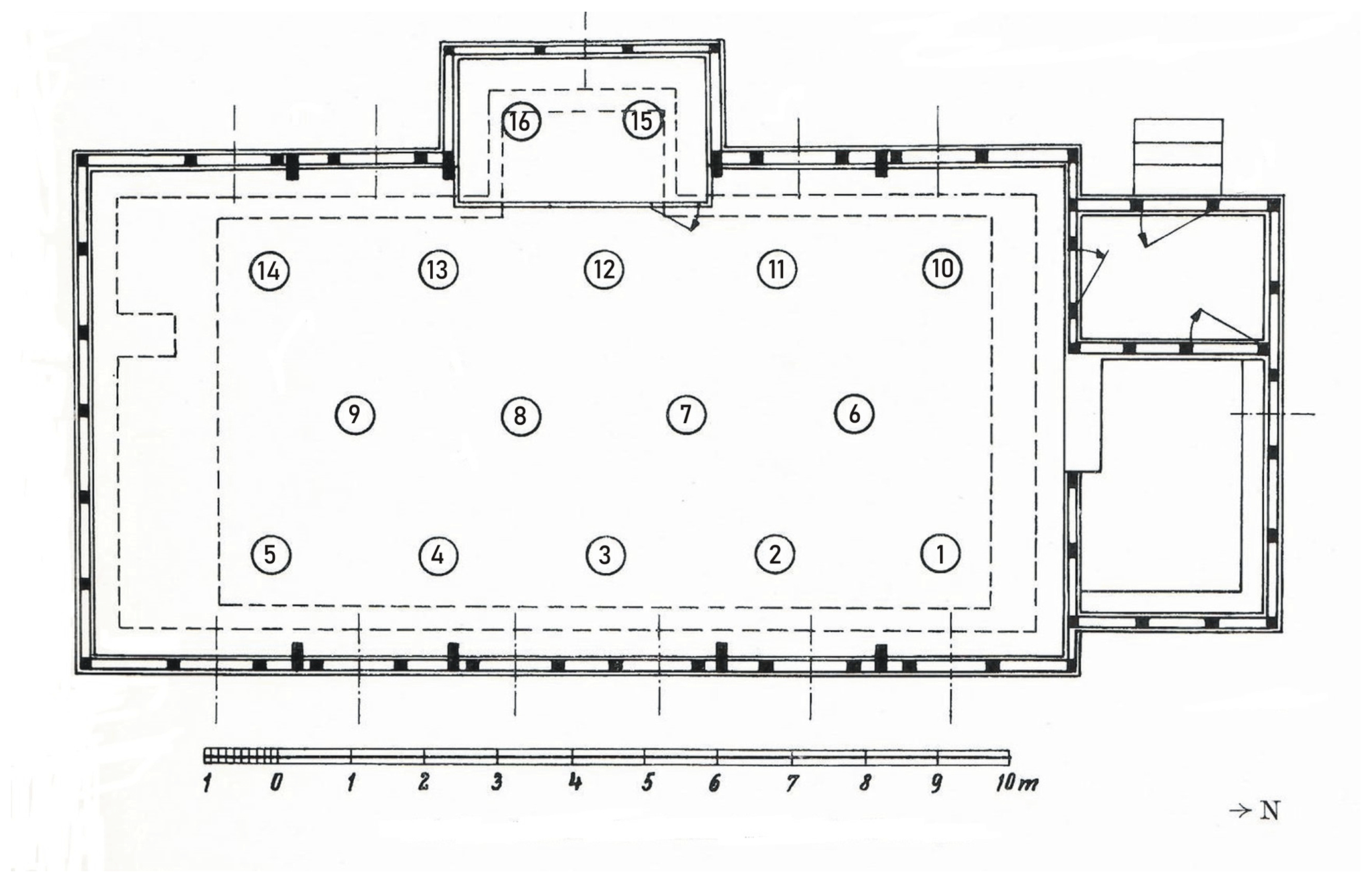
Figure 9Ground plan of the absolute house. Source: Bock (1939).

Figure 10Ground plan of the variation house. Source: Bock (1939).
Adolf Schmidt intended a separate heating system on the basis of gas for the variation house and tile stoves for the absolute house. But finally, a central heating system for the heating of both magnetometer buildings was constructed. A separate solid-clinker-constructed heating house (Fig. 11 shows a photo of the building) containing the coal-burning boiler, the pumps and the coal storage at a suitable distance to the observation buildings was used during the cold seasons. The connection pipes and the radiators in the observation houses were made from copper. Only the insulating corridor of the variation house is heated by means of the warm-water heating system. The instrument rooms are heated by means of thermoelectric-controlled electric radiators. The annual temperature variation in the rooms is less than 0.5°C.
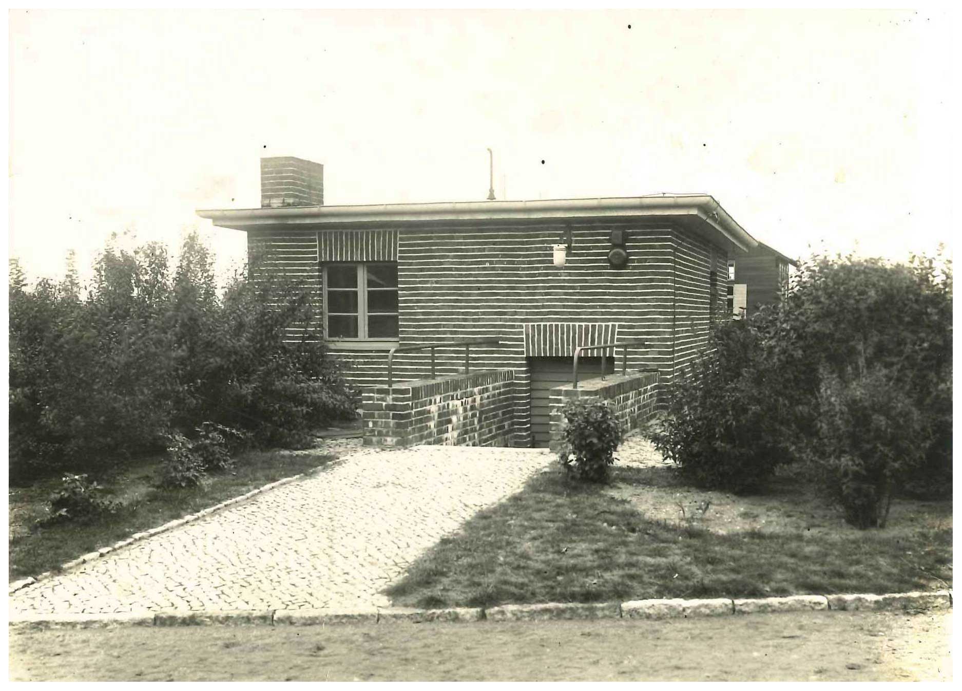
Figure 11Photo of the north-east corner of the heating house. Source: Helmholtz Centre Potsdam – GFZ.
The two Seddin Observatory buildings were re-erected on magnet-free concrete foundations in 1932 (Nippoldt, 1934). The former Seddin variation house was intended to be used as a laboratory, which is still its function in the present day. It was also connected to the central heating system operated from the heating house. Its basement has a crawl space for cable placement. The former Seddin absolute hut was first called the “observation hut”. Later, it was renamed as the “small hut”. A photo of its present situation is shown in Fig. 5 in Linthe (2023b). Figure 12 shows a photo of the observatory buildings, viewed from the apartment and service house.

Figure 12Photo of the Niemegk Adolf Schmidt Geomagnetic Observatory compound, taken in 1933 from the apartment and service house. From left to right: laboratory (former Seddin variation house), variation house, heating house (partly hidden by a tree), absolute house, Niemegk church, outdoor pillar and observation hut (former Seddin absolute house). Source: Bock (1939).
In 1960, the construction of a new building as an electric laboratory was finished (Fanselau, 1962a). Figure 13 shows a view from the attic floor of the main building on the laboratory. In 1961, two more measurement huts were constructed at the observatory compound, one of them for housing the sensor of the proton magnetometer. In 1963, an observation hut for the telluric recordings and a little solid building for housing a small computer were added (Fanselau, 1964). During the next year, a wooden building housing the measurement centre was constructed.

Figure 13View from the attic floor of the main building on the electric laboratory. Source: Helmholtz Centre Potsdam – GFZ.
In 1967, the construction of a solid house, called the workshop building, housing the precision mechanical workshop, three guest rooms, three offices, two meeting rooms, a kitchen and a photographic laboratory, was finished (Fanselau, 1968). Figure 14 shows a photo of the building. In the same year, the computer building was extended.
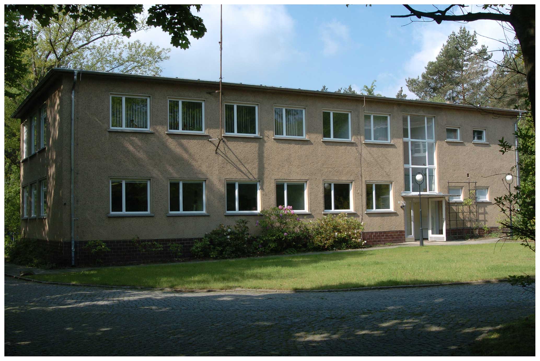
Figure 14Photo of the workshop building, view from the north-east. It was taken in 2005. Source: Helmholtz Centre Potsdam – GFZ.
Further buildings were constructed at different times for different purposes. Finally 26 buildings existed on the observatory compound. Figure 15 shows the ground plan of 2003. Of the 26 buildings, 1 building did not exist at this time any more. Three more buildings, which were not in use any more, were removed in 2004. Figure 16 shows the present ground plan of the observatory compound.
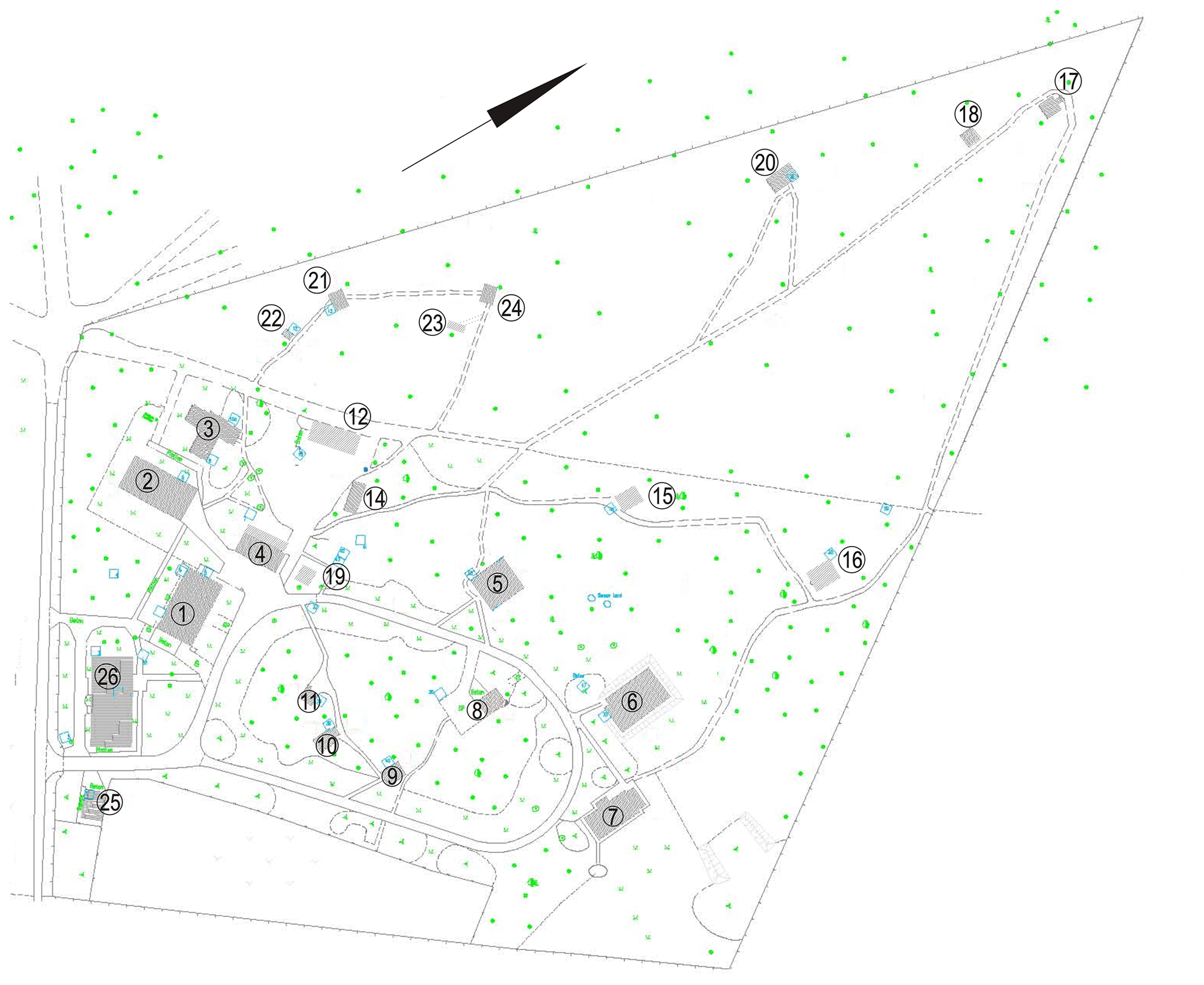
Figure 15Ground plan of the observatory compound, situation in 2003. The assignment of the buildings to their numbers is as follows: 1 – main building, 2 – electric laboratory, 3 – computer centre, 4 – storage house, 5 – magnetic laboratory, 6 – variation house, 7 – absolute house, 8 – heating house, 9 – small hut, 10 – adjustment hut, 11 – thermal adjustment hut, 12 – garage, 14 – equipment shed, 15 – proton magnetometer hut, 16 – control hut no. 1, 17 – coil hut no. 1, 18 – control hut no. 2, 19 – measurement centre, 20 – telluric hut, 21 – coil hut no. 2, 22 – small control hut, 23 – control hut no. 3, 24 – coil hut no. 3, 25 – power unit house and 26 – workshop building. Source: Helmholtz Centre Potsdam – GFZ.
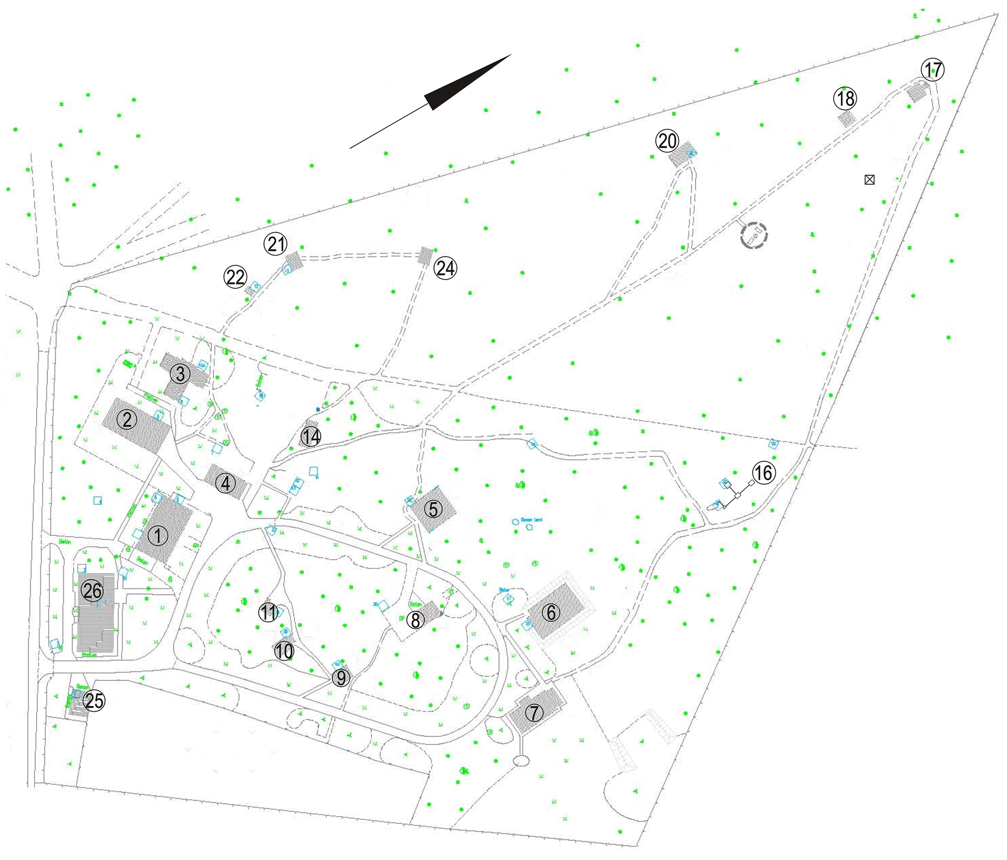
Figure 16Ground plan of the observatory compound, present situation. The assignment of the buildings to their numbers is as follows: 1 – main building, 2 – electric laboratory, 3 – computer centre, 4 – storage house, 5 – magnetic laboratory, 6 – variation house, 7 – absolute house, 8 – heating house, 9 – small hut, 10 – adjustment hut, 11 – thermal adjustment hut, 14 – equipment shed, 16 – container variometer, 17 – coil hut no. 1, 18 – control hut no. 1, 20 – telluric hut, 21 – coil hut no. 2, 22 – small control hut, 24 – coil hut no. 3, 25 – power unit house, 26 – workshop building. Source: Helmholtz Centre Potsdam – GFZ.
The buildings numbered 1, 4, 5, 6, 7, 8, 9, 10 and 11 were declared historic monuments in 2004.
2.2 Niemegk Observatory instruments
The instruments used before in Potsdam and in Seddin were transported step by step to Niemegk and installed at the new site. Brief descriptions of the instruments and the measurement procedures can be found in Appendix A.
2.2.1 Absolute measurements
The three theodolites for the measurement of declination and horizontal intensity, Wanschaff, Bamberg and Schmidt, as well as the oscillation box Wanschaff, have got suitable conditions in the new absolute house due to the large number of pillars (14). The two Earth inductors, Schulze no. 1 and no. 65, as well as the appropriate galvanometers, are positioned on separate pillars. Figure 17 shows an interior view of the absolute house. The figure caption gives the assignment of the visible instruments to the pillars.
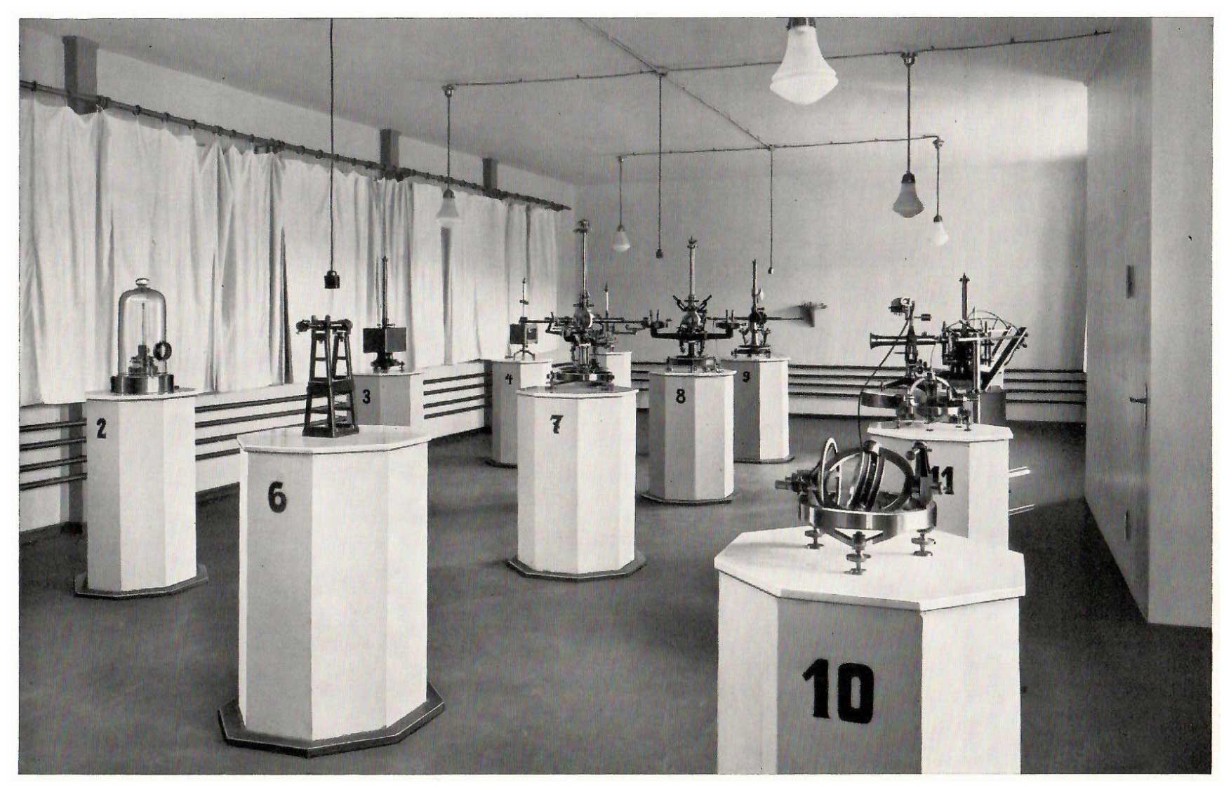
Figure 17Interior view of the absolute house in 1932. The assignment of the visible instruments to the pillars is as follows: 2 – Galvanometer for the Earth inductors, 3 – Wanschaff oscillation box, 4 – Schulze oscillation box (Fürstenfeldbruck), 5 – Schulze no. 65 theodolite (Fürstenfeldbruck), 6 – Collimator (azimuth mark in case of invisible towers), 7 – Bamberg theodolite, 8 – Schmidt theodolite, 9 – Wanschaff theodolite, 10 – Schulze no. 550 Earth inductor (Fürstenfeldbruck), 11 – Schulze no. 1 Earth inductor, 13 – Schulze no. 65 Earth inductor and 14 – Schulze no. 541 journey theodolite. Source: Bock (1939).
The accuracy of the oscillation measurements was significantly improved by means of the construction of a photoelectric oscillation measurement facility in 1933 (Fanselau, 1933).
The Bamberg theodolite, the Wanschaff oscillation box, the photoelectric oscillation measurement facility and the standard magnets for the measurement of the horizontal intensity were lost in 1945 (Fanselau's preliminary remark in Richard and Wiese, 1954). New standard magnets were purchased in 1950. A new oscillation box was constructed by the observatory workshop. The lost photoelectric oscillation measurement facility was replaced by a new one, established in 1954 (Schmidt, 1956). A further Earth inductor was delivered by Mating & Wiesenberg, Potsdam (Richard and Wiese, 1954). The new positions of the instruments in the absolute house are given in the caption of Fig. 17.
From 1959 onward, several homemade proton magnetometers were in use for permanent measurements of the total intensity (Schmidt, 1962; Wiese, 1962). In 1970, a Russian caesium magnetometer was employed on pillar no. 1 in the absolute house. Comparisons to the proton magnetometer measurements were made (Lengning et al., 1973). Later on, a homemade vector proton magnetometer was installed on pillar no. 1 in the absolute house.
In 1992, two DI (declination–inclination) flux instruments on the basis of the Zeiss Theo 010B theodolite equipped with the Bartington Mag-01H fluxgate magnetometer were purchased and employed. Figure 18 (left) shows the DI flux on pillar no. 8 of the absolute house, with the Niemegk church tower in the background. The absolute measurements by means of these instruments were performed on pillar nos. 2 and 5 in the absolute house. Measurements of the total intensity were carried out on the same pillars by means of the GEM GSM19 Overhauser proton magnetometer (Best et al., 1993). The GSM19 is depicted in Fig. 18 (right).
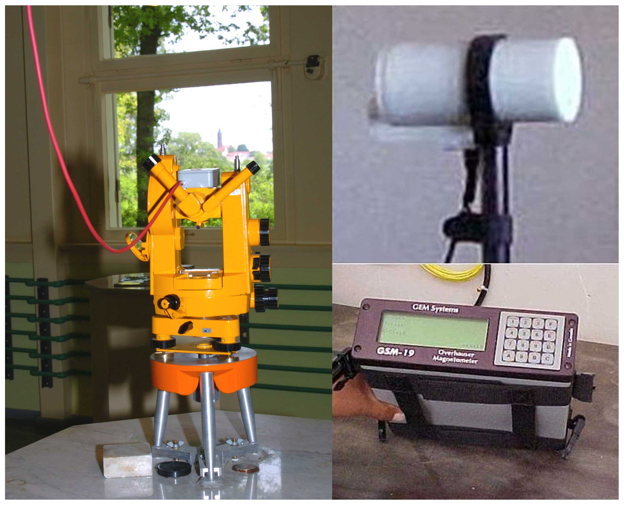
Figure 18DI flux on pillar no. 8 of the absolute house with the Niemegk church tower in the background (left) and Overhauser proton magnetometer GSM19 (right, sensor top and electronic unit bottom). Source: Helmholtz Centre Potsdam – GFZ.
Brief descriptions of the instruments and the measurement procedures of the modern instruments can be found in Appendix A as well.
2.2.2 Variation recordings
In the beginning, variometers that formerly operated in Potsdam or Seddin were installed in Niemegk. The differences of Potsdam and Seddin compared to Niemegk are as follows: instead of baseline interruptions (Potsdam and Seddin), vertical lines on the photographic recordings were used as hourly time marks in Niemegk, controlled by the non-magnetic pendulum clock, which was moved from Potsdam. In Potsdam and Seddin, gas lamps were used for the illumination of the photographic recording. In Niemegk, from the beginning, electrical lamps powered by batteries in the main building were used exclusively for the photographic recording.
The Mascart variometers, used before at the Potsdam observatory for the recording of the declination (D), horizontal (H) and vertical intensity (Z), were mounted after some modifications and alignments in the north-east room of the Niemegk variation house. An instrument for recording the inclination (I) was added. The projected sensitivities were 2 nT mm−1 for H and Z and 0.4 arcmin mm−1 for D and I. The recording equipment (made by Askania, Berlin-Friedenau), with four drums for the photographic paper, used two of the drums for two variometers, together on one paper sheet, with a recording speed of 2 cm h−1. The further two drums allowed for the recording of the same variometers of selectable recording speeds of 6 or 24 cm h−1 (Bock, 1935).
Figure 21 shows one of the first test photographic recordings of the horizontal intensity, declination and vertical intensity of the time interval from 08:00 on 25 March 1931 to 07:20 on 26 March 1931 (Greenwich local mean time, GMT), taken at the Niemegk Adolf Schmidt Geomagnetic Observatory.
The variometer set used formerly in Seddin, including the photographic recording equipment for recording of the north (X) component, east (Y) component and vertical (Z) intensity, was placed in the Niemegk north-west room in the same arrangement as at Seddin. Figure 19 shows an interior view of this room. The tracks on the photographic recordings are described in Linthe (2023b) and remain unchanged.
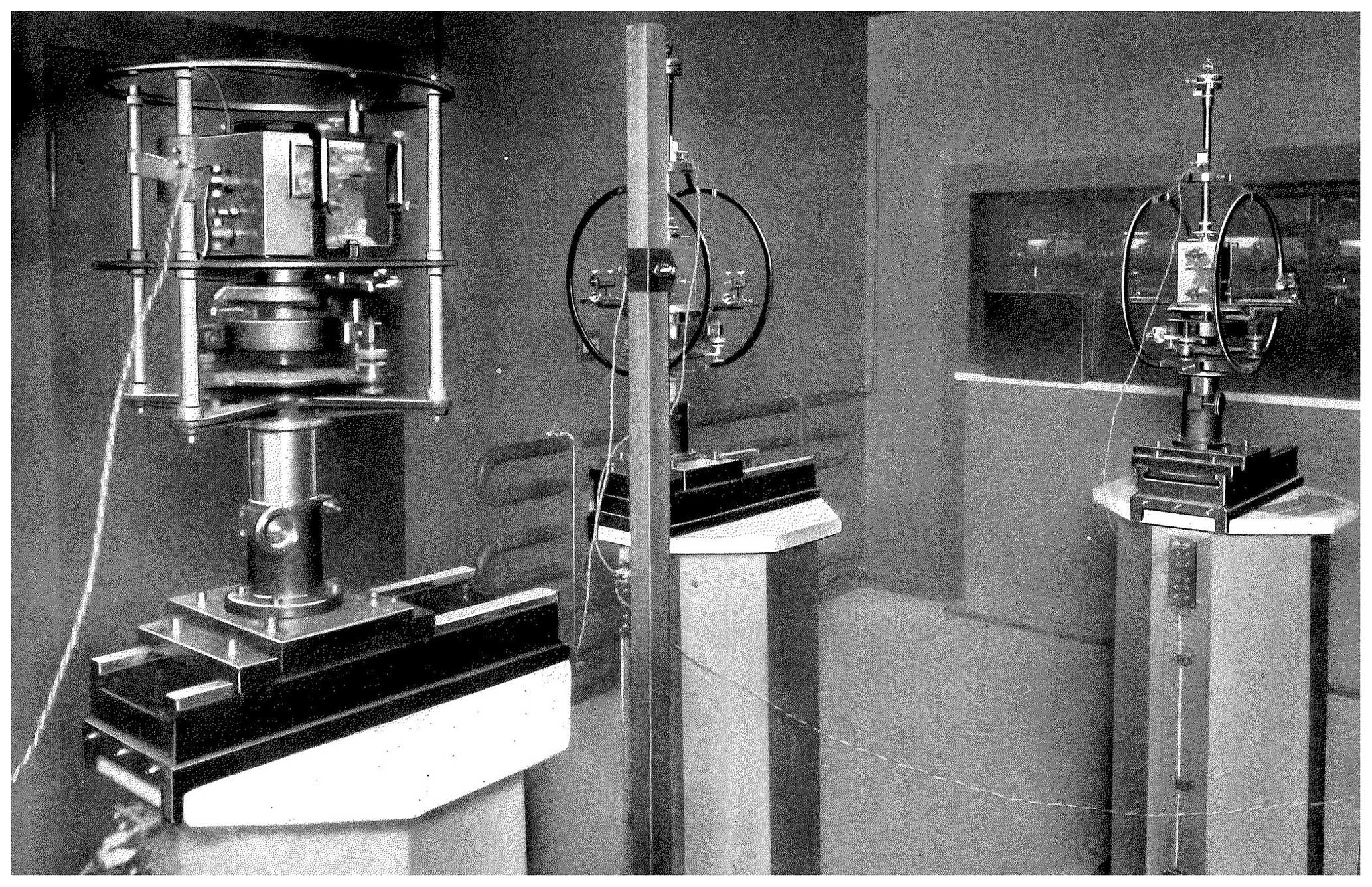
Figure 19Photo of the interior of the north-west room of the variation house. Source: Bock (1939).
All the variometers in the north-east and north-west room were equipped with Helmholtz coils for the galvanic scale value determination.
In the south room, a declination (D), horizontal intensity (H) and vertical intensity (Z) variometer set was operated. From 1937 onward, a special recording unit (Schmidt, 1926) with a plotting speed of 4 mm min−1 was operated, which had already been in use in Seddin (Linthe, 2023b).
From 1938 onward, an instrument set of reduced sensitivity (25 nT mm−1 for H and Z and 5 arcmin mm−1 for D), a so-called storm variometer, was operated in the west room of the magnetic laboratory.
Because of the damage of buildings and instruments and loss of three variometer sets in 1945 due to World War II, only a provisional operation of the north-east system was restarted in February 1946. Details are described in Sect. 2.3. Figure 22 shows the first photographic recordings after the observation gap of the horizontal intensity, declination, vertical intensity and room temperature of the time interval from 10:30 GMT on 27 February 1946 to 09:00 GMT on 28 February 1946. The principle of recording the variations of different components of the Earth's magnetic field and temperatures on the same magnetogram, which is clearly visible in this figure, remained at the Niemegk Observatory.
In 1948, a new set of variometers of reduced sensitivity (storm variometer) was installed (Fanselau and Wiese, 1956). In 1950, a new variometer set, made by Mating & Wiesenberg, Potsdam, was installed in the south room of the variation house, recording the north component (X), east component (Y) and vertical intensity (Z). Also, in 1950, a new variometer system was installed in the north-west room, recording H, D and Z, which had been made in the observatory workshop.
The operation of the storm variometer in the magnetic laboratory was stopped in 1951 and replaced by a journey recording unit (Fanselau, 1951), which was operated additionally in the north-west room of the variation house. It was finally replaced by a new H–D–Z storm variometer set in the north-east room of the variation house in 1954 (Wiese, 1957).
In 1960, a new piece of recording equipment made by Mating & Wiesenberg, Potsdam, was installed for the north-west variometer system.
In 1965, a special paper-economising three-component photographic recording using specially constructed recording equipment was started in the magnetic laboratory (Fanselau and Grafe, 1963). It was in operation until 1970 (Lengning et al., 1971).
Digital recording vector proton magnetometers were constructed during the 1970s at the observatory. Their continuous operation at the Niemegk Observatory and at the remote station Warnkenhagen (on the Baltic Sea coast, north-west German Democratic Republic, GDR) started in 1976 (Lengning et al., 1977). In 1978, a digital recording scalar proton magnetometer was installed at the remote station Sosa in the Ore Mountains (south GDR). All the proton magnetometers recorded at a sampling rate of 1 min on eight-channel punched tapes. The operation of these instruments at the remote stations was terminated in 1991. The termination of the Niemegk vector proton magnetometers followed in 1994.
In 1993, an M390 “automatic geomagnetic observatory”, made by the French company GEOMAG, consisting of the VM390A fluxgate magnetometer, the GEM SM90R Overhauser proton magnetometer, the electronic unit and a METEOSAT transmitter, was installed and operated continuously in the variation house. The recorded data were transmitted to INTERMAGNET and stored on a 3.5 in. floppy disk. The operation of this instrument was terminated in 2006.
In 1995, the three-component fluxgate magnetometer FGE, made by the Danish Meteorological Institute Copenhagen, and the Overhauser proton magnetometer GSM19, made by GEM Systems, Richmond Hill, Canada, were employed in the variation house. They were controlled by the homemade MAGDALOG data logger (Best and Linthe, 1996). Figure 20 shows a photo of the FGE. The GSM19 is depicted in Fig. 18, right. Two more sets of this digital recording system of the same configuration were installed in the variation house in 2000. These instruments are the present variation recording systems of the Niemegk Adolf Schmidt Geomagnetic Observatory. Only the GSM19 instruments were replaced by the GSM90 Overhauser proton magnetometers. The FGE vector sensors are located in the south room, and the scalar sensors are placed in the north-east room of the variation house. A further digital recording system was installed in 2008 in an underground container (no. 16 in Fig. 16).
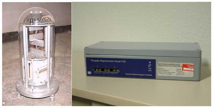
Figure 20Fluxgate magnetometer FGE sensor (left) and electronic unit (right). Source: Helmholtz Centre Potsdam – GFZ.
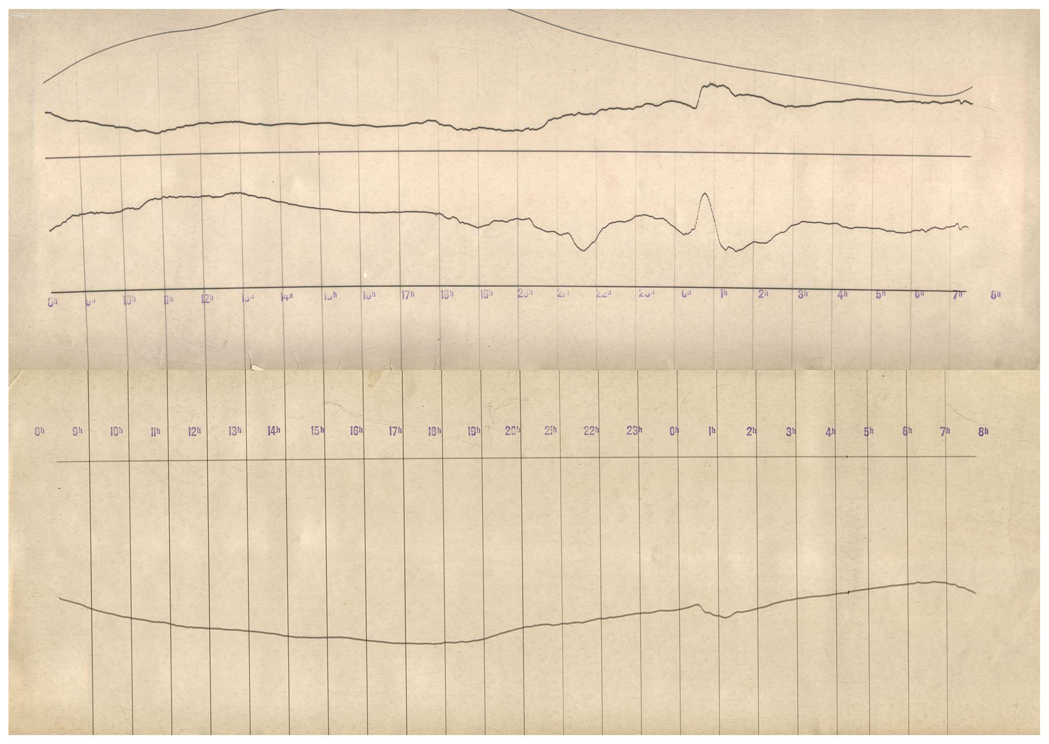
Figure 21One of the first photographic recordings of the horizontal intensity and declination (top) and the vertical intensity (bottom) of the time interval from 08:00 GMT on 25 March 1931 to 07:20 GMT on 26 March 1931, taken at the Niemegk Adolf Schmidt Geomagnetic Observatory. Source: Helmholtz Centre Potsdam – GFZ.

Figure 22First photographic recordings after the operation gap caused by World War II of the horizontal (H) and vertical (Z) intensity and declination (D) of the time interval from 10:30 GMT on 27 February 1946 to 09:00 GMT on 28 February 1946 taken at the Niemegk Adolf Schmidt Geomagnetic Observatory. Source: Helmholtz Centre Potsdam – GFZ.
In 1996, a further three-component fluxgate magnetometer, made by MAGSON, Berlin, was installed in a measurement hut. The recorded data were transmitted manually by means of a laptop (Best and Linthe, 1997). The operation of this instrument was terminated in 2005.
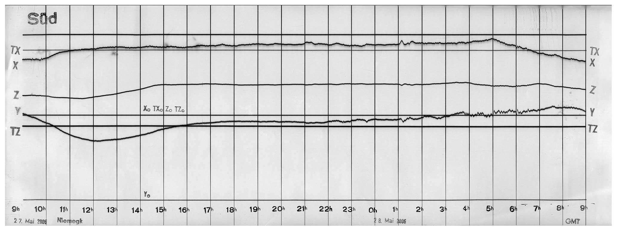
Figure 23Last photographic recordings of the north (X), east (Y) component and the vertical (Z) intensity of the time interval from 09:00 GMT on 27 May 2006 to 09:00 GMT on 28 May 2006, taken at the Niemegk Adolf Schmidt Geomagnetic Observatory. Source: Helmholtz Centre Potsdam – GFZ.
The photographic recordings were continued until the photographic paper was finished. Figure 23 shows the last photographic recordings of the north component (X), east component (Y) and vertical intensity (Z) and two room temperatures of the time interval from 09:00 GMT on 27 May 2006 to 09:00 GMT on 28 May 2006, taken at the Niemegk Adolf Schmidt Geomagnetic Observatory.
Brief descriptions of the classical and modern instruments for recording of the variations can be found in Appendix A as well.
2.3 Operation of the Niemegk Observatory
On 30 May 1930, a caretaker and a technician moved into their apartments of the main building. Richard Bock (1899–1961), as the observer, followed them on 1 December 1930 (Nippoldt, 1931a). These three employees operated the observatory on-site. All the data evaluation took place at the institute headquarters in Potsdam.
In 1931, groundwater was already welling up in the variation house, which dramatically degraded the operation conditions of the instruments. The seasonally changing groundwater level was not considered carefully enough during the planning phase. An expensive and time-consuming drainage construction (finished in November 1931) drained off the groundwater (Bock, 1950). Together with a ventilation system, the situation for the instruments was finally improved. But the wooden beams and shelves of the floor construction were so damaged that in 1934, both a chemical conditioning of the beams and a replacement of the shelves were necessary (Bock, 1937, 1950). These measures required removal of all the instruments from the building. The replacement recordings took place in the magnetic laboratory, which was employed at the end of 1933 after its demolition in Seddin and re-erection in Niemegk. After a more or less provisional operation of the observatory from 1931–1934, due to the construction defect of the variation house, finally from 1935 onward, a normal situation started.
The absolute measurements were performed by means of the Wanschaff theodolite on pillar no. 9 for the declination (D) and horizontal intensity (H), supplemented by the oscillation box on pillar no. 3 and by means of the Schulze no. 1 Earth inductor on pillar no. 11 for the inclination (I). The associated galvanometer was placed on pillar no. 2.
From 1936 onward, plots of typical variations, such as bay disturbances, sudden storm commencements (SSCs) and further characteristic trends of the geomagnetic variation field, were included in the yearbooks. In 1937, plots of pulsations followed. For the publication in the yearbooks, the photographic recordings were scale-transformed using a specially developed pantograph, constructed by Adolf Schmidt (Luyken, 1909).
From 1937 onward, the magnetic activity K index, proposed by Julius Bartels (1899–1964), was published regularly in the yearbooks (Bartels, 1938). The index was internationally adopted on Bartels' suggestion at the Washington conference of the International Association for Terrestrial Magnetism and Electricity (IATME) in 1940.
In 1944, World War II was already influencing the Niemegk territory. Bombings and aeroplane shots attacked the town. The storming of the town of Niemegk by Soviet tank, artillery and infantry forces took place in April 1945 (Dalitz, 1995). The last magnetograms were taken from the recording equipment on 20 April 1945. The absolute house was heavily damaged by an artillery strike, whereby the instruments were totally contaminated. A further artillery strike damaged the transformer house; therefore the power supply was interrupted until September 1945. The most serious consequence was the instrument loss, commandeered by the victor force (Fanselau and Wiese, 1954).
Only under strenuous efforts was the war damage reversed step by step. The operation of the observatory needed to be re-established completely anew. The artillery strike of the absolute house caused a lot of shrapnel to be trapped in the wooden parts, which needed to be individually and extensively discovered and removed in addition to the building repair (Fanselau and Wiese, 1956). The variometer recordings were restarted on 27 February 1946, first only provisionally. Due to the loss of the standard magnets, the absolute measurements of the horizontal intensity were performed using a magnet of low quality.
On the basis of the newly purchased or constructed instruments, a new determination of the absolute level of the Earth's magnetic field values took place from 1950–1952 (Richard and Wiese, 1954). Thus the azimuth values of the outdoor pillar, of some of the pillars in the absolute house, and of both the ones in the small hut with respect to the Niemegk church and water tower and further distant village church towers were geodetically newly determined.
Up to this time, only the Wanschaff theodolite had been in permanent use for the determination of the declination and horizontal intensity. From this time onward, these measurements were performed by means of both the theodolites (Wanschaff and Schmidt). Their results were averaged.
On the basis of the experimental studies of proton magnetometers, started in 1950, equipment for the permanent measurement of the total intensity was established (Schmidt, 1962; Wiese, 1962). This was in use from 1958 onward. From 1959 onward, the results were published in a special yearbook table, demonstrating the difference of the proton magnetometer measurements to the classical ones. The total intensity measurements were performed through manual operation on the outdoor pillar Waldpfeiler (“forest pillar”, in hut no. 15 in Fig. 15) as well as regularly on workdays in the absolute house on pillars no. 15 and 16. From 1965 onward, such measurements were also carried out in parallel in the absolute house on pillar no. 2. The data of the proton magnetometer measurements of all installed instruments were compared regularly from then on. In 1962, a survey of the total intensity in the absolute house was carried out (Schmidt, 1963) to find out magnetic anomalies. Neglectable anomalies were found.
The observatory results on the basis of the proton magnetometer measurements were of higher accuracy in comparison to the data achieved from inclination measurements by means of the Earth inductor. Therefore, consequently, from 1966 onward, the measurements of the total intensity using proton magnetometers were directly used for the baseline calculation. The inclination measurements using the Earth inductors were only used for level checks and were finally terminated (Grafe, 1968).
In 1968, the first magnetic recording instruments with digital output were employed (Fanselau, 1969).
2.4 Development of the observatory after German reunification in 1990
After the positive evaluation of the Niemegk Adolf Schmidt Geomagnetic Observatory by the German Science and Humanities Council, it was decided to integrate the observatory into the GeoForschungsZentrum (GFZ) Potsdam, which was founded on 1 January 1992.
The observatory started in 1931 with three on-site employees. This situation did not change until the time immediately after World War II. Gerhard Fanselau lost his apartment in Berlin due to bombing attacks on the city. He took a free apartment at the observatory. He first arranged the repairs of the demolished buildings and instruments and restarted the observation service. Next, he facilitated a comprehensive development of the observatory. He initiated the instrument development and established a scientific working group in Niemegk. He looked after the logistic base and recruited the necessary number of employees: both technicians and scientists. Even after Fanselau's retirement in 1969, the number of employees increased up to 55 persons during the 1980s. With the foundation of the GeoForschungsZentrum (GFZ), the number of employees decreased dramatically but more or less in a socially acceptable way. The Unification Treaty determined the closing of all institutes of the Academy of Sciences of the German Democratic Republic on 31 December 1991. New positions for scientists and technicians were opened during the foundation of the GFZ in the course of the year 1991. Former employees of the observatory, who were not considered for any new observatory position, went into retirement, changed to other enterprises, took alternative positions within the GFZ or took project positions.
From 1992 onward, all the historical computers were replaced step by step by modern personal computers. The complete variation recording was transmitted into digital mode by installing homemade MAGDALOG data loggers and using glass fibre data transmission. The complete observatory data are stored in a database and secured by suitable backup systems.
From 1992 onward, absolute measurements were performed regularly by means of the DI flux (declination, inclination) and the GEM GSM 19 (total intensity) in parallel with the classical ones. The results of both measurements were compared.
The Niemegk Adolf Schmidt Geomagnetic Observatory became an IMO (INTERMAGNET Magnetic Observatory) in 1993. In 1994, the survey of the total intensity of the pillars in the absolute house was repeated (Linthe, 1995). The new survey confirmed the results of Schmidt (1963).
From 1994 onward, digital observatory data were published on 3.5 in. floppy disks as well as in the yearbook tables (Best and Linthe, 1995).
After the successful comparisons of the absolute measurements by means of the classical instruments and the modern ones over 4 years, in 1996, the classical absolute measurements were stopped. From this time on, the observatory level was based on the DI flux and the Overhauser proton magnetometer on pillar no. 8. This instrument change caused a jump in the horizontal and vertical intensity of the observatory level. The classical photographic recordings were continued. But the observatory data were based on the digital recordings of the three-component fluxgate magnetometer FGE (Best and Linthe, 1997).
A new determination of the azimuth values of the outdoor pillar and several absolute house pillars was carried out in 1997 (Förster, 1998).
The Bundesamt für Seeschifffahrt und Hydrographie Hamburg (BSH) decided to terminate the operation of the Erdmagnetisches Observatorium Wingst with 1 January 2000. The GeoForschungsZentrum Potsdam (GFZ) and the BSH agreed in a contract to continue the observations in Wingst. The BSH remained responsible for the management of the compound and the buildings, while the GFZ took over the operation of the instruments and the scientific responsibility (Linthe and Schulz, 2005). Wingst Observatory was finally under complete responsibility of the GFZ in 2014. From 2000 onward, joint yearbooks of both observatories were published. The yearbook publication was terminated with the 2003 one.
2.5 Affiliations, observers and directors, i.e. heads, of the observatory
The Niemegk Adolf Schmidt Geomagnetic Observatory was affiliated to different scientific or administrative organisations. Table 1 shows the complete affiliation history. Table 2 contains the list of the scientific directors, i.e. heads, of the observatory. The observers responsible are listed in Table 3.
Table 1Affiliations of the Niemegk Adolf Schmidt Geomagnetic Observatory.
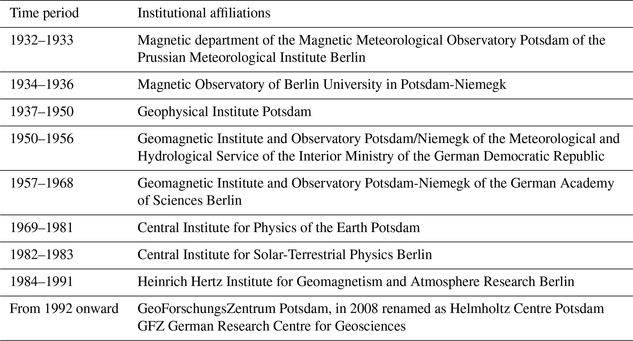
Table 2Scientific directors, i.e. heads, of the Niemegk Adolf Schmidt Geomagnetic Observatory.
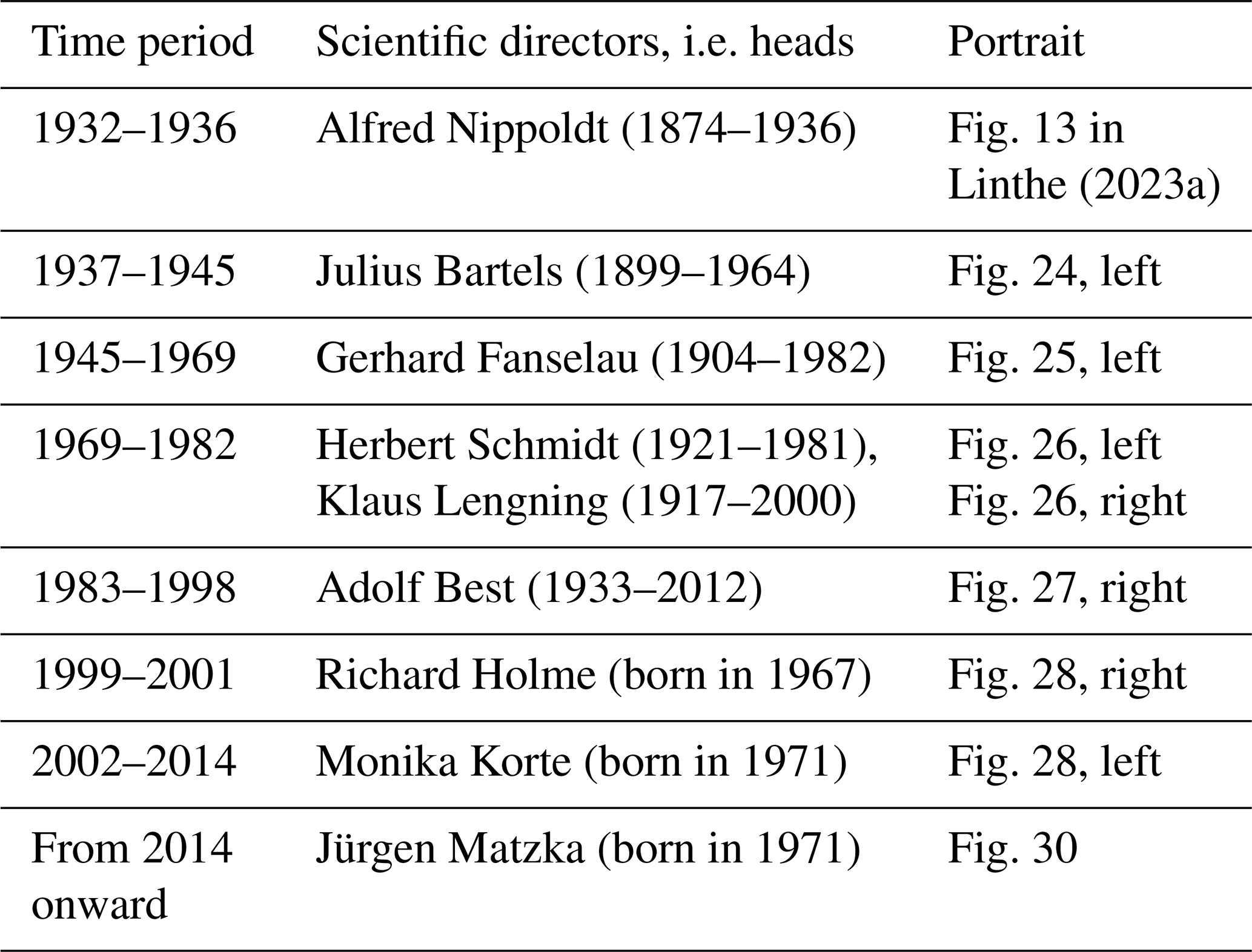
Table 3Observers of the Niemegk Adolf Schmidt Geomagnetic Observatory.

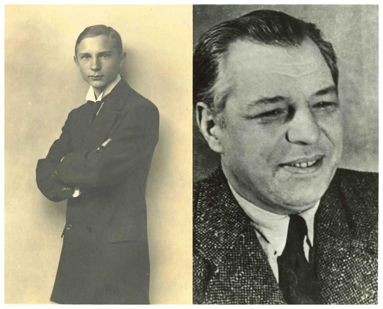
Figure 24Julius Bartels' portrait (left) and Richard Bock's portrait (right). Source: Helmholtz Centre Potsdam – GFZ.
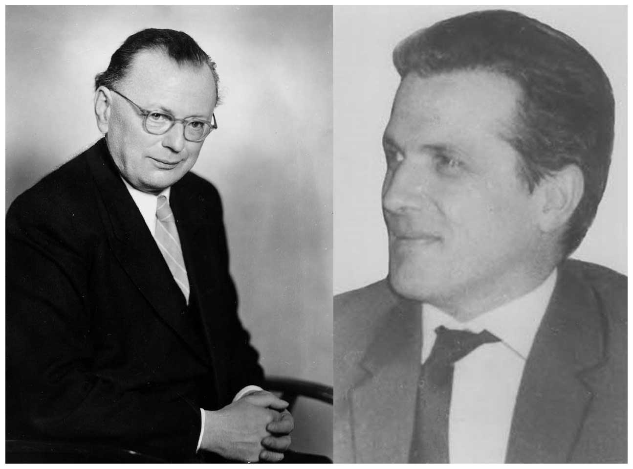
Figure 25Gerhard Fanselau's portrait (left) and Horst Wiese's portrait (right). Source: Helmholtz Centre Potsdam – GFZ.
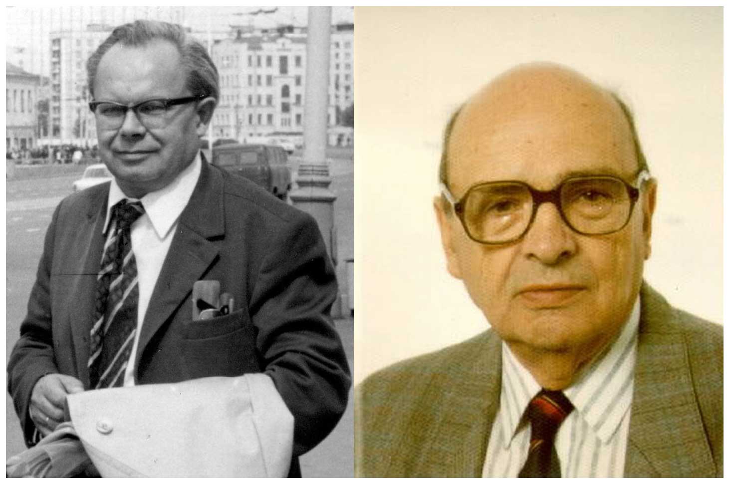
Figure 26Herbert Schmidt's portrait (left) and Klaus Lengning's portrait (right). Source: Helmholtz Centre Potsdam – GFZ.
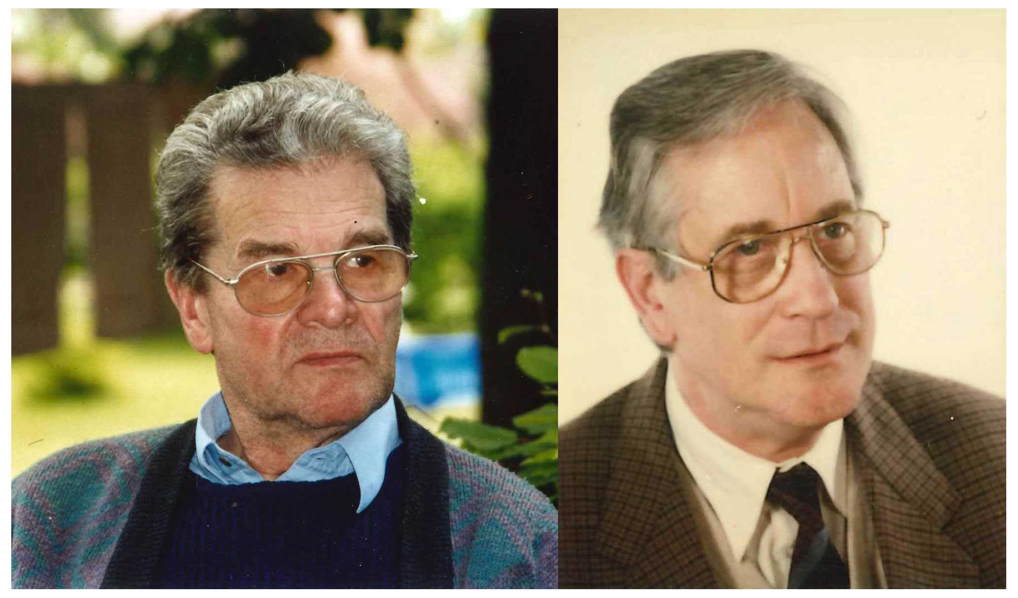
Figure 27Armin Grafe's portrait (left) and Adolf Best's portrait (right). Source: Helmholtz Centre Potsdam – GFZ.

Figure 28Monika Korte's portrait (left) and Richard Holme's portrait (right). Source: Helmholtz Centre Potsdam – GFZ.

Figure 29Eberhard Ritter's portrait (left) and Hans-Joachim Linthe's portrait (right). Source: Helmholtz Centre Potsdam – GFZ.
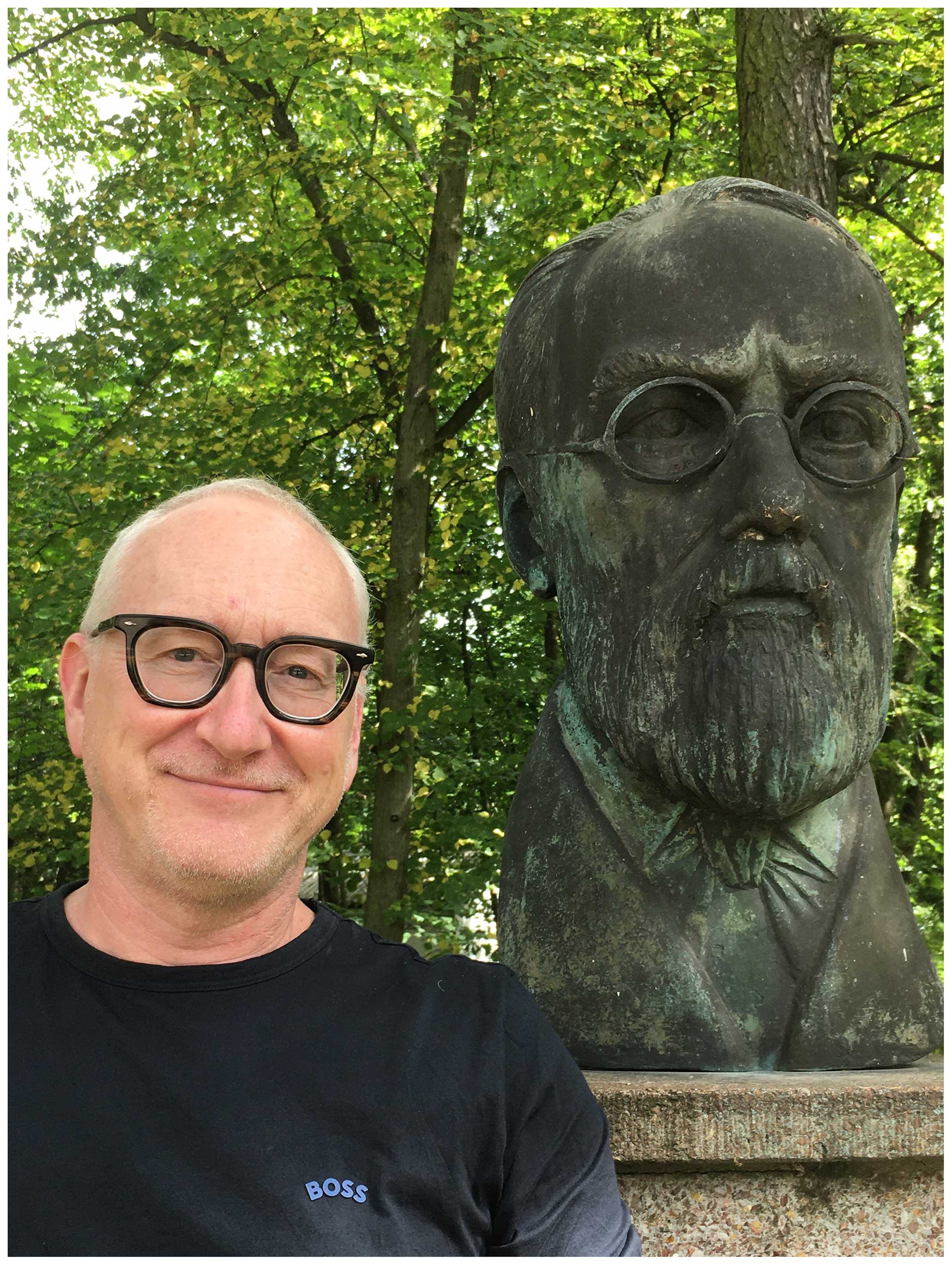
Figure 30Jürgen Matzka's portrait next to the Adolf Schmidt bust at the Niemegk Observatory compound. Source: Helmholtz Centre Potsdam – GFZ.
Magnetic observatory data can be achieved only by combining continuous recordings of the temporal variations of the Earth's magnetic field with periodical absolute measurements. The absolute measurements are necessary to calibrate the variation instruments (variometers). The classical instruments, which were in use in Niemegk until the 1990s, had been constructed mainly according to the principle of a suspended magnet.
Variometers for recording of horizontal elements, for instance the north (X) or east component (Y), horizontal intensity (H), or declination (D), consist of a bar magnet suspended by means of a vertical thread. The magnet can only move in one direction, corresponding to the element to be recorded. The instrument for the vertical component (Z) needs a magnet able to move vertically. Practically, this is achieved by mounting the magnet on a balance. Both the horizontal and vertical variometers have a mirror on their face side.
During the beginning of magnetic observatories, the position of the magnet was manually read by means of a telescope. The observer's sight was reflected by the mirror at the magnet on a scale. Already during the 19th century, the photographic recording was constructed. A light beam from a lamp was reflected by the mirror at the magnet on a photographic paper, which was fixed on a drum, driven by clockwork, which took one turn per day. The photographic paper was to be changed once per day and developed in the normal way. The product was called a magnetogram. The variometer rooms needed to be kept in complete darkness. Only for the short time of paper change was weak red light allowed.
In the beginning of photographic recording, the light source was gas lamps. They were used in Potsdam and Seddin. In Niemegk, electrical lamps, powered by batteries, were used. In Seddin and Niemegk, Helmholtz coils, mounted on every variometer, were used for scale value determination. Using glass scales, the positions of the tracks on the magnetograms were read and converted into magnetic units using the scale values. Comprehensive details on classical instruments and measurement practices can be found in Wiese et al. (1960).
Absolute measurements are performed using magnetic theodolites. By means of them, the declination (D) and the horizontal intensity (H) can be determined. They consist of a horizontal circle, a telescope, a magnet (the so-called magnetic needle) and a vertical thread. It is placed on a stable pillar. It is necessary to know the geodetical azimuth of the pillar with respect to an azimuth mark. The geodetical azimuth is the angle between the geographic north direction and the sight line from the measurement pillar to the azimuth mark. The declination measurement starts with a bearing by means of the telescope to the azimuth mark and the reading of the circle. Then the magnetic needle is fixed at the vertical thread. The natural Earth's magnetic field will force the magnetic needle to point to magnetic north. The observer needs to turn the theodolite until the magnetic needle is parallel to the axis of the telescope by observing the face side of the magnetic needle. Now the horizontal circle needs to be read. The difference of both the readings is the declination.
For the measurement of the horizontal intensity, the theodolite needs to have one or two bars at the same level at which the magnetic needle is placed. A so-called deflection magnet of a known magnetic force is put on the bar in a fixed distance perpendicular to the magnetic needle. From the angular difference of a bearing with and without the deflection magnet, H can be calculated. A second method of H measurement is the oscillation method. The deflection magnet is fixed in its centre on a vertical thread and forced to make torsion movements. The horizontal intensity can be calculated from the oscillation period. The performance of two independent methods for the same parameter allows drifts in the magnetic force of the deflection magnet to be eliminated. The determination of the oscillation period can be done by the “eye and ear” method. The use of suitable opto-electronic equipment yields more accurate results (Schmidt, 1956).
In ancient times, the inclination (I) was determined by a dip needle, which is a magnetic needle that can move in a vertical direction. The position of the needle with respect to a vertical circle gives the value of I. A more precise instrument is the Earth inductor. It uses a zero method. The position of a rotating coil is to be found in which no current in the coil is induced caused by the Earth's magnetic field. A sensitive galvanometer is connected to the coil as the indicator for the induced current. The tilt and azimuth of the coil axis can be adjusted and read on reference circles. The read tilt is the inclination.
Beginning with the 1940s, new measurement methods and instruments for the Earth's magnetic field were developed. In around 1990, instruments using the new principles were able to be used in the magnetic observatories. Three principles found wide application in the observatory practice:
-
Coils of many windings without cores were used for the recording of short periodic variations. The voltages induced in the coils were recorded on photographic paper by galvanometers. Later on, coils with high permeable cores (search coil magnetometers) were used with digital recording.
-
A further principle is the saturation core or fluxgate magnetometer. The working principle of this instrument is based on the saturation of a transformer core. In this situation, primarily odd harmonics of the excitation frequency are produced. When, in addition to the alternating excitation field, a DC component of the environmental magnetic field also acts on the core, even harmonic signals appear too. By means of suitable electronic circuits, these even harmonics are detected and converted into an output voltage proportional to the Earth's magnetic field component in the direction of the sensor core.
-
A third principle is the so-called proton magnetometer. It consists of a vessel filled with a proton-rich liquid, a surrounding coil and electronic control circuits. The coil is used in two modes: in the first one, a strong DC current flows through the coil. The induced magnetic field forces the protons in the liquid sample to align their spin axis along the coil field. After switching off the DC current, the protons start to reorient their spin axis towards the ambient magnetic field by performing a precession motion. The resulting precession frequency is proportional to the ambient magnetic field strength. In this phase the coil is used to pick up the proton precession signal, and the electronics measures the derived frequency. The best results are achieved when the direction of the applied DC field is approximately perpendicular to the Earth's magnetic field.
Further principles were developed, but their use in magnetic observatories is limited. Only the optical pumping is quite useful, which is based on an atomic effect of the electrons. The construction of such magnetometers is extremely expensive (Bloom, 1962; Pulz and Jäckel, 1998).
For absolute measurements, DI flux magnetometers are widely in use. These consist of a non-magnetic theodolite, with a horizontal and a vertical circle and equipped by a fluxgate sensor, connected to its electronic unit. The axis of the fluxgate is adjusted as well as possible parallel to the telescope axis and serves as an indicator for the direction of the Earth's magnetic field. It is possible to determine the declination (D) and the inclination (I). The instrument is placed on a stable pillar. It is necessary to know the geodetical azimuth of the pillar with respect to an azimuth mark. The geodetical azimuth is the angle between the geographic north direction and the sight line from the measurement pillar to the azimuth mark. The declination measurement starts with a bearing by means of the telescope to the azimuth mark and the reading of the circle. The next step is to align the telescope as exactly as possible horizontally. Then the telescope is rotated until the display of the magnetometer shows zero. That means that the direction of the Earth's magnetic field in the horizontal plane is perpendicular to the telescope. The horizontal circle is to be read. The difference of both the readings, considering the azimuth value and 90°, is the declination. The inclination can be determined by tilting the telescope until the display of the magnetometer shows zero. The inclination results from reading the vertical circle, considering 90° (because the position of the telescope is perpendicular to the direction of the Earth's magnetic field in the vertical plane). Both angles are determined by means of a zero method, which eliminates offset errors and non-linearities of the magnetometer. The misalignments of the sensor axis with respect to the telescope axis are eliminated by means of performing the D and I measurements in four positions each.
The total intensity (F) of the Earth's magnetic field is determined by means of a proton magnetometer. The two angles, D and I, and the scalar value, F, together determine the field vector. The natural variation of the field during the time of the absolute measurement is taken into account by considering the variometer data. The instruments and the procedure are described in detail in Jankowski and Sucksdorff (1996).
On the occasion of the International Polar Year 1932–1933, equipment for recording of telluric currents was installed, consisting of two lines in the geographic directions north–south and east–west, both of 1000 m length, funded by the Rockefeller Foundation (Bock, 1950). The electrodes were lead plates. The east and south electrodes were located in the observatory compound and the west and north electrodes at an appropriate distance in neighbouring forests. The recording was performed by galvanometers on photographic paper, located in the laboratory. It is unknown as to when the recordings were stopped; recordings are not anymore available. In 1949, activities for the re-establishment of telluric recordings were started. Potential-free copper and blue vitriol electrodes were developed in 1953 at the observatory (Lengning, 1958). In 1956, the continuous recording was started (Lengning, 1960). From 1957 onward, further lines of different directions and lengths were installed and operated. Presently, only the two 1000 m geographically oriented lines are still in operation; they have been using digital recording since 2001 (Linthe and Schulz, 2007).
In 1952, induction coil variometers were installed and operated. Rectangular coils of many windings and big dimensions located in the absolute house were in use for the north and east component. The vertical intensity was detected by a wire fixed at the fence around the observatory compound. The coils were connected to galvanometers recording on photographic paper of a speed of 4 mm min−1 in the south room of the variation house (Wiese, 1956). Due to the enlargement of the observatory compound in 1952, a horizontal coil of 50 m circumference was installed as vertical intensity sensor (Wiese, 1958). The recording galvanometer was moved in 1957 to the west room of the variation house (Wiese, 1960). In 1971, the coreless coils were replaced by cylindrical ones with cores of high permeability of small diameter and 2 m length (search coils). An electronic amplifier unit, developed during the period 1965–1970 with photographic recording, was employed (Auster, 1972). In 1999, the photographic recording was replaced by digital recording. The equipment is still in operation.
Around 1948, a field balance on the basis of a tape-suspended magnet was constructed in the precision mechanical workshop of the observatory (Fanselau, 1948). This instrument dramatically improved the knife-edge field balance according to Adolf Schmidt. In the beginning of the 1950s, the development of instruments on the basis of new principles began: fluxgate and proton magnetometers. The tape-suspended field balance was elaborated more and more, and different modifications were constructed. A project was started to construct a chamber of constant magnetic field (Konstanthaltung) for instrument calibration (Fanselau, 1953). In 1952, the compound of the observatory was enlarged to a size of 5.2 ha to ensure the undisturbed operation of the Earth's magnetic field observations besides the further projects of instrumental development. A measurement and adjustment hut for the field balance production and two huts for the constant magnetic field chamber (one containing a three-component cylindrical Helmholtz coil system of big dimensions) were constructed (Fanselau, 1955).
In preparation of the International Geophysical Year (IGY) 1957, in 1953, three satellite stations began to be constructed in Warnkenhagen (north-west German Democratic Republic), Ückermünde (north-east GDR) and Herrnhut (south-east GDR) for geomagnetic and geoelectric recordings (Fanselau, 1956). The data of the satellite stations were intended to be used for scientific investigations of the distribution of the Earth's magnetic field over the GDR and local differences of the secular variation. The Herrnhut station was terminated in 1961 (Fanselau, 1962b). The Ückermünde station existed until 1965 (Fanselau, 1966). The closure of the two stations happened for logistic and financial reasons.
In 1956, the precision mechanical workshop was moved from the basement of the main building to the storage house, suitably modified for this purpose. The instrumental equipment of the satellite stations was continued in 1956 (Fanselau, 1957).
In 1956, a project to study the local gradient of the Earth magnetic field was started. For this purpose four magnetometer stations were constructed at the corner points of a 7 km square, geographically oriented (Fanselau, 1958). Each station was equipped with three geographically oriented photo-electrically compensated field balances with analogue paper recording. The north-western station was located at a distance of 200 m south-westward of the observatory compound.
Different measurement expeditions were performed in connection with the IGY: from 1956 onward, repeat station and magnetotelluric measurements in the territory of the GDR and some eastern European countries. In 1961, an expedition to study the effect of a solar eclipse on the Earth's magnetic field took place in Romania and Bulgaria (Fanselau, 1962a). A “Phänomen Granit 30K” van (Fig. C1 shows a photo of it) was in use for all expeditions. The van was fully equipped with any necessary instruments.
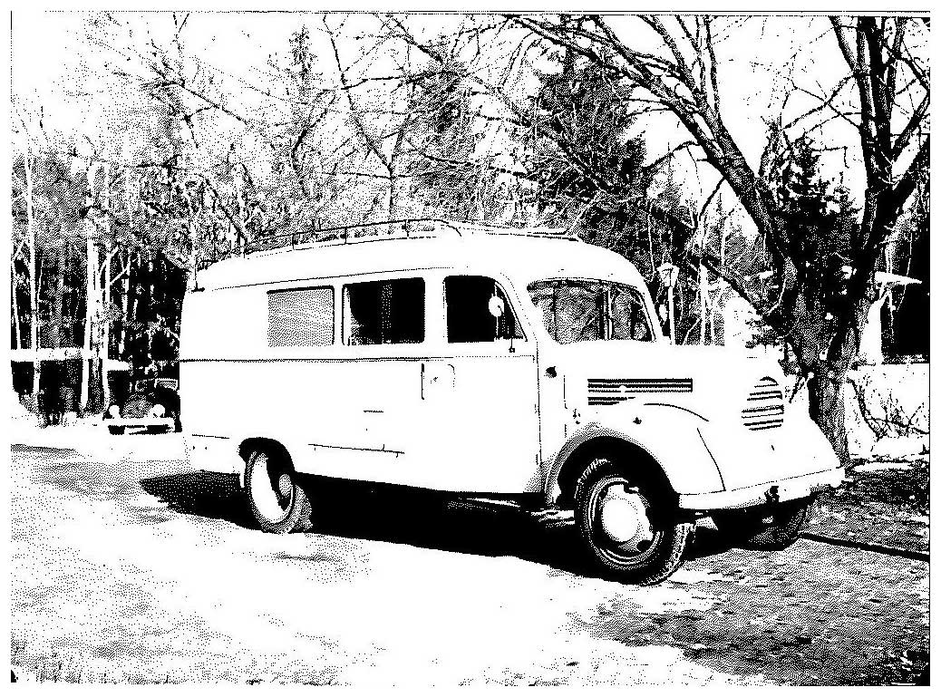
Figure C1Photo of the Phänomen Granit 30K survey van. Source: Helmholtz Centre Potsdam – GFZ.
From 1953–1962, repeat station measurements were carried out at 1762 stations in the territory of the German Democratic Republic. The results were reduced relating to 1957.5 (Bolz, et al., 1969).
In 1963, electronic data processing started by means of the purchase of a small SER 2 computer, produced by the company Cellatron in Zella-Mehlis, Thuringia, German Democratic Republic (Fanselau, 1964). Equipment for digitisation of photographic magnetic recordings was developed and employed, together with the small computer. The yearbook in 1965 was the first one produced by means of the use of the SER 2 (Schmidt, 1967).
From 1970 onward, the observation programme of the remote station Warnkenhagen was expanded. Besides the sensitive-scale variometer set, a set of lower-sensitivity values and a scalar proton magnetometer were installed. Also, telluric and induction coil magnetometer recordings were taken into operation (Lengning et al., 1973). From 1976 onward a vector proton magnetometer was in operation. At a further remote station, located at Sosa in the Ore Mountains, a scalar proton magnetometer was installed in 1978.
In 1972, a piece of digital data acquisition equipment based on modules of the R300 computer, produced by the company Robotron in Radeberg, near Dresden, German Democratic Republic, was installed for the recording of 1 Hz sampled five channels' magnetic and telluric data in the enlarged computer house (building no. 3 in Fig. 15) of the observatory (Lengning et al., 1973).
Again, in 1975, a process control computer, PRS4000, also produced by the company Robotron, was installed in the enlarged computer house of the observatory (Lengning et al., 1976). It was intended to be used for the direct digital data acquisition from the geomagnetic recording instruments and for data processing. It was in operation during the 3 regular world days for the online processing of the signals of the search coil magnetometers. From 1976 onward, the yearbook tables were produced by means of this computer. All the digital proton magnetometer recordings on punched tapes were inserted and stored on the PRS4000.
In 1983, a MPS4944 microcomputer was employed for the continuous online processing of the signals of the search coil magnetometers. The MPS4944 was produced by the scientific tool building of the Central Institute for Nuclear Research in Rossendorf near Dresden, German Democratic Republic, which is today the Helmholtz-Zentrum Dresden-Rossendorf. The necessary software was developed at the observatory (Lenners et al., 1984).
The remote stations Warnkenhagen on the Baltic Sea coast and Sosa in the Ore Mountains were closed in June 1991 due to the changed conditions caused by German reunification in 1990.
On the basis of contributions of the observatories Fürstenfeldbruck, Niemegk and Wingst, the first magnetic map of the whole of Germany after German reunification was published in 1995 (Beblo et al., 1995).
The homemade vector proton magnetometer on pillar no. 1 in the absolute house was in operation until 1998, but its results were never in use for the observatory data (Linthe, 2000).
A long tradition of instrument development existed at the Niemegk Adolf Schmidt Geomagnetic Observatory. The precision mechanical workshop and the electronic laboratory ensured excellent conditions. The staff reduction of the observatory caused by German reunification decreased the instrumental development base. But several further activities took place. Eberhard Pulz intensively worked on the design of optically pumped magnetometers, using international experiences. He designed for instance a caesium–potassium tandem magnetometer (Pulz and Jäckel, 1998). Also on the basis of his international contacts, a caesium–helium magnetometer was built (Pulz and Linthe, 1998). The scalar caesium–potassium magnetometer is still in test operation on pillar no. 15 of the absolute house. On the basis of the experience with these scalar instruments, later on, a vector magnetometer was developed (Pulz et al., 2009). The sensor of the instrument is positioned in the small hut (house no. 9 in Fig. 16). The instrument is still in permanent test operation.
The Institute of Geophysics and Extraterrestrial Physics of the Technical University Braunschweig proposed the development of an automatic absolute measurement system on the basis of the experience with the satellite magnetometer calibration (Auster et al., 2007; Hemshorn et al., 2009). The precision mechanical workshop of the Niemegk Adolf Schmidt Geomagnetic Observatory manufactured the hardware and installed it on pillar no. 5 in the absolute house. The software was designed by the Brunswick and Niemegk teams. The instrument is still in permanent test operation.
In 1949, Julius Bartels suggested to the international geomagnetic community the establishment of an international service of producing a general index that describes the geomagnetic planetary activity caused by solar corpuscular radiation. He called this activity index Kp, planetarische Kennziffer (Bartels, 1949). His suggestion was accepted by the international community and was continuously produced under his leadership at the Geophysical Institute of Göttingen University. After Bartels' death in 1964, his successor Manfred Siebert continued the service. Regarding his retirement, Siebert asked for any responsible successor institution within the Deutsche Geophysikalische Gesellschaft (German Geophysical Society). The Niemegk Adolf Schmidt Geomagnetic Observatory was ready to take over the service. Therefore, on 1 January 1997, the Kp Index Service of the International Service of Geomagnetic Indices was taken over from the Geophysical Institute of Göttingen University (Best and Linthe, 1999). The index is of global relevance and has not lost any significance and use through the years.
Several scientific and technical conferences were held from time to time at the observatory.
On 11 and 12 November 1960 a commemorative event was held at Humboldt University Berlin, honouring Adolf Schmidt's 100th birthday on 23 July 1960 and the 150th anniversary of the university. A further memorial on the occasion of the 30th anniversary of the observatory took place on 21 December 1960 (Fanselau, 1962a).
On the occasion of the 50th anniversary of the Niemegk Adolf Schmidt Geomagnetic Observatory, the international symposium “Current problems of geomagnetic research” took place at the observatory and at a holiday camp 20 km away. Almost 100 participants attended the symposium. About 50 scientific presentations were given, and 13 participants performed comparison measurements by means of their own instruments (Kautzleben, 1981).
On 29 April 1983, the Central Institutes for Physics of the Earth and Solar-Terrestrial Physics performed a colloquium honouring Gerhard Fanselau, former director of the Geomagnetic Institute Potsdam and Niemegk Adolf Schmidt Geomagnetic Observatory, in Potsdam. Seven scientific presentations were given (Lengning et al., 1983).
From 22–26 September 1986, the Heinrich Hertz Institute for Atmosphere Research and Geomagnetism Berlin performed the IAGA Symposium on Space–Time Structure of the Geomagnetic Field in Lutherstadt Wittenberg, including a visit of the Niemegk Adolf Schmidt Geomagnetic Observatory (Mundt, 1987).
From 23–28 April 1990, the International Symposium, 100 Years Geomagnetic Observatory Potsdam–Seddin–Niemegk, was held in Potsdam. A total of 66 scientists from 14 countries participated. In total, 44 scientific presentations were given. The participants visited the historic magnetic measurement buildings on the Telegrafenberg Potsdam and the Niemegk Adolf Schmidt Geomagnetic Observatory (Mundt and Best, 1991; Best et al., 1991, 1992).
On 7 and 8 September 1996, the INTERMAGNET Executive Council and Operations Committee held a meeting at the Niemegk Adolf Schmidt Geomagnetic Observatory.
The observatory organised the VIIth IAGA Workshop on Geomagnetic Instruments and Data Acquisition from 9–14 September 1996. A total of 95 scientists from 33 countries participated in the workshop. During the practical part, 45 absolute measurements were performed at the observatory. During the scientific part, 48 papers and 12 posters were presented in the Alba Hotel Wittenberg. The results and papers were published (Best and Linthe, 1998).
In collaboration with the German Esperanto League, a commemoration took place on Adolf Schmidt's 50th year of death at the observatory on 17 October 1994 (Best and Wollenberg, 1994).
On 23 July 2010, Adolf Schmidt's 150th birthday and the 80th anniversary of the opening of the Niemegk Adolf Schmidt Geomagnetic Observatory were celebrated in Niemegk by the Deutsche Geophysikalische Gesellschaft and the Helmholtz Centre Potsdam (Jacobs and Linthe, 2010). In total, 30 participants attended the festivities.
The Adolf Schmidt Niemegk Geomagnetic Observatory maintained close collaboration with many international geomagnetic observatories. Mutual scientific visits took place in large number. Comparison measurements were carried out at Niemegk and international observatories to compare the accuracy of the instruments and the observers.
In 1996, the Hurbanovo Geomagnetic Observatory (Slovakia) was supported by providing new instruments for the absolute measurements and variation recordings funded by the Volkswagen Foundation. The Hurbanovo staff was trained in the use of the instruments by Hans-Joachim Linthe.
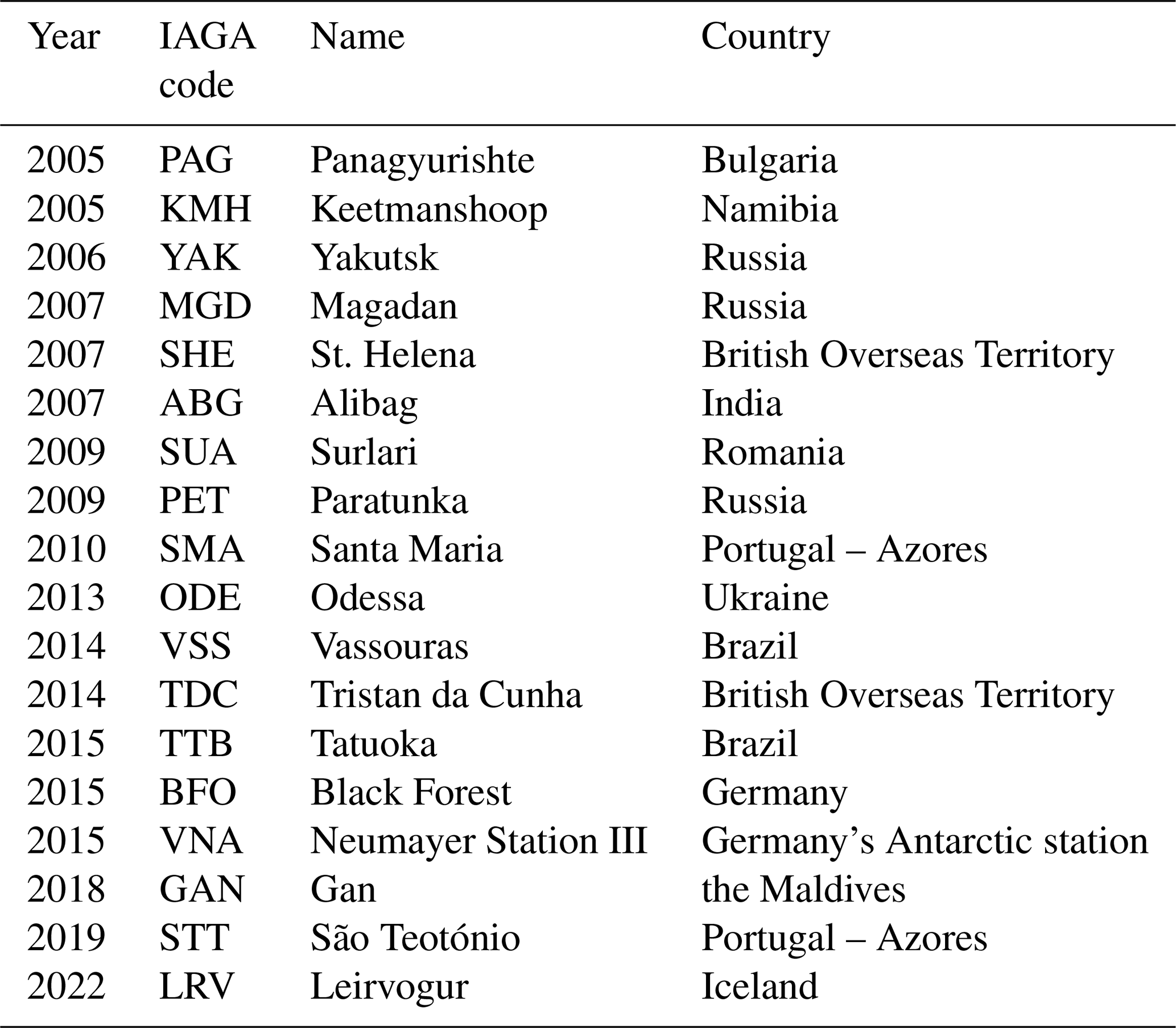
From 2005 onward, new geomagnetic observatories were established or existing ones equipped with modern instruments on the basis of international agreements, sponsored by Helmholtz Centre Potsdam – GFZ. The observatories are listed in Table E1.
Meetings of German-speaking observers were held from time to time in Niemegk or at other observatories. Students' education of several German universities is supported in the form of excursions and practical training. Guided tours through the observatory are offered to any interested persons.
Since 1961, the observatory has regularly instructed trainees in precision mechanics and electronics.
The agency for military surveying of the German Federal Armed Forces regularly calibrate their magnetic instruments at the observatory and consult on magnetic measurement instruments and measurement practice.
Table E1List of the observatories, newly established or equipped with modern instruments on the basis of the international collaboration with Helmholtz Centre Potsdam – GFZ, Niemegk Adolf Schmidt Geomagnetic Observatory.
Walter Zander (1922–1998) was awarded a long-service award by the International Association of Geomagnetism and Aeronomy (IAGA) in 1993 for his outstanding contribution to produce high-quality data by the Niemegk Adolf Schmidt Geomagnetic Observatory (IAGA News, 1993). Figure F1 shows the handing over of the medal to Walter Zander by Heinrich Soffel (national representative of Germany for IAGA). The same award was presented to Hans-Joachim Linthe in 2015 for his dedicated effort for the operation of the Niemegk Adolf Schmidt Geomagnetic Observatory and the modernisation or new establishment of international observatories (Mandea, 2015). He was further an active member of the INTERMAGNET Operations Committee (2003–2014) and chair of the IAGA Working Group V-OBS (2003–2007). In Fig. F2, Linthe (right) is seen together with Kathy Whaler (IAGA President 2011–2015, left) and Mioara Mandea (IAGA Secretary General 2009–2019).
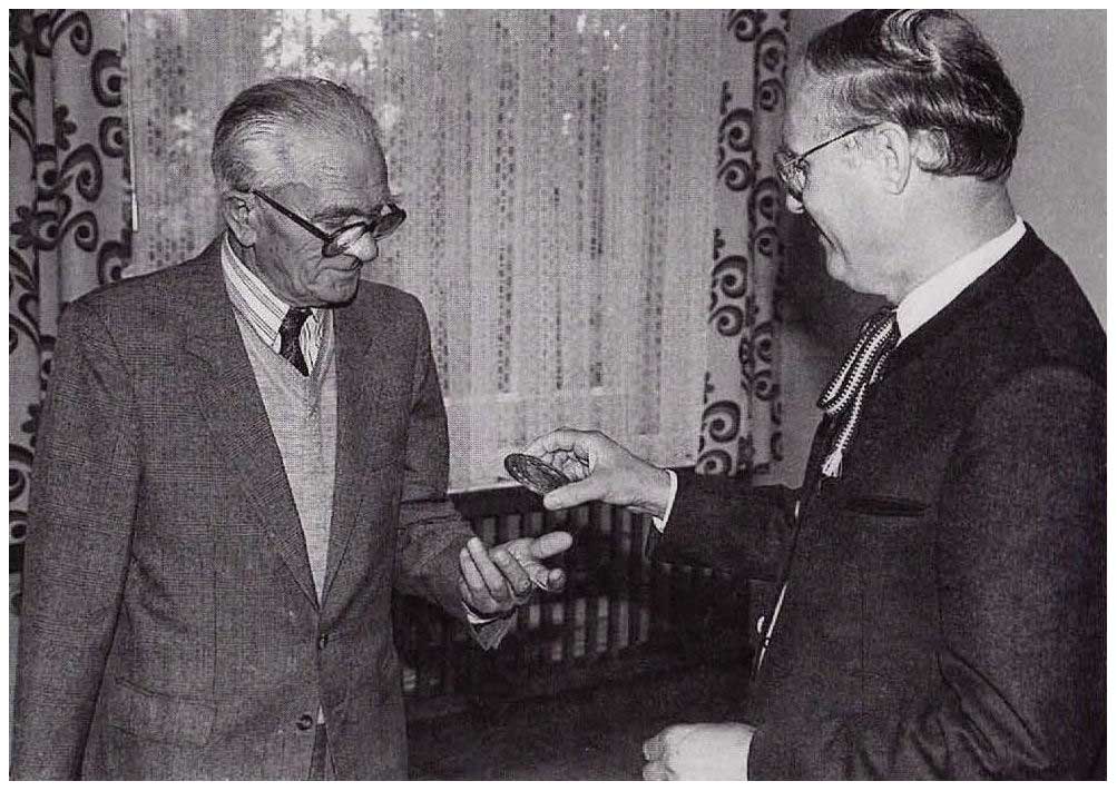
Figure F1Heinrich Soffel, the National Representative of Germany for IAGA (right), hands over the Long Service Award of IAGA to Walter Zander (left). Source: IAGA News no. 32, https://iaga-aiga.org/data/uploads/pdf/newsletter/iaganews_32_1993.pdf (last access: 4 September 2024).

Figure F2From left to right: Kathy Whaler (IAGA President 2011–2015), Mioara Mandea (IAGA Secretary General 2009–2019) and Hans-Joachim Linthe after receiving the IAGA long-service medal. Source: Mandea (2015), https://iaga-aiga.org/data/uploads/pdf/newsletter/iaganews_52.pdf (last access: 4 September 2024).
Max Eschenhagen classified days into five categories regarding the magnetic activity (Eschenhagen, 1894). He introduced gamma (γ) as a unit in geomagnetism (Eschenhagen, 1896) and discovered pulsations called Elementarwellen (“elementary waves”) (Eschenhagen, 1897).
Adolf Schmidt calculated the geomagnetic potential for the epoch 1885 (Schmidt, 1895) and is known for the transformation of spherical harmonics into different coordinate systems (Schmidt, 1889), construction of the knife-edge field balance (Schmidt, 1915), simplification of Eschenhagen's classification of days by introduction of three categories, introduction of the international character figure Ci and its inter-diurnal variability (Schmidt, 1916), and construction of a new magnetic theodolite for an improved method of the deflection experiment (Bock and Schmidt, 1928).
Julius Bartels introduced the activity index K (Kennziffer) in 1939 from Niemegk recordings (Bartels, 1938) and is known for the introduction of the planetary activity index Kp, planetarische Kennziffer (and the derived indices ap, Ap, Cp and C9), the measure used most internationally for characterising geomagnetic activity (Bartels, 1949).
Richard Bock conducted Magnetische Reichsaufnahme – the repeat station campaign over Germany (known at the time as the Deutsches Reich) together with Friedrich Burmeister and Friedrich Errulat (Bock et al., 1948) and is known for high merits in the changeover of the observation service from Potsdam and Seddin to Niemegk (Bock, 1950).
Gerhard Fanselau improved the field balance using a suspended balance (Fanselau, 1948).
Horst Wiese discovered the north German conductivity anomaly together with Otto Meyer (Wingst), which was the basis of his theoretical contributions to magnetotellurics – “Wiese arrow” (Wiese, 1965).
Herbert Schmidt constructed several observatory instruments, including proton magnetometers, fluxgates and induction coil variometers (Schmidt, 1962; Wiese, 1962), and introduced data processing into observatory practice (Fanselau, 1964).
Codes of the observatory are in general not publicly available. All are designed for a very special purpose and not useful for any external use.
Geomagnetic data from the geomagnetic observatories Potsdam, Seddin and Niemegk are available at the World Data Centre (WDC) for Geomagnetism, Edinburgh (https://wdc-dataportal.bgs.ac.uk/, WDC, 2024), a member of the World Data System (WDS) (https://worlddatasystem.org/, WDS, 2024). More recent data from Niemegk Geomagnetic Observatory are available from INTERMAGNET at https://intermagnet.org/ (last access: 9 October 2024).
The author has declared that there are no competing interests.
Publisher's note: Copernicus Publications remains neutral with regard to jurisdictional claims made in the text, published maps, institutional affiliations, or any other geographical representation in this paper. While Copernicus Publications makes every effort to include appropriate place names, the final responsibility lies with the authors.
This article is part of the special issue “History of geophysical institutes and observatories”. It is not associated with a conference.
Kristian Schlegel strongly encouraged me to write this paper. I am very thankful to him for his patience. I further thank the Helmholtz Centre Potsdam, the GFZ German Research Centre for Geosciences, which rendered it possible for me to write the paper using its resources. I am especially thankful to Jürgen Matzka, group leader of the Geomagnetic Observatories for Geomagnetism Section of the GFZ, for giving me the opportunity to work at the Niemegk Adolf Schmidt Geomagnetic Observatory. Since my official retirement at the end of 2014, I have had the chance to use an office, a computer and all the observatory publications to collect the necessary information.
This paper was edited by Kristian Schlegel and reviewed by Hermann Lühr and one anonymous referee.
Auster, H.-U., Mandea, M., Hemshorn, A., Korte, M., and Pulz, E.: GAUSS: Geomagnetic Automated System, in: Proceedings of the XIIth IAGA Workshop on Geomagnetic Observatory Instruments, Data Acquisition and Processing, Belsk, Poland, 19–24 June 2006, Publications of the Institute of Geophysics, Polish Academy of Sciences, Warszawa, Poland, Monographic Volume C-99, 49–59, ISBN-83-88765-70-1, 2007.
Auster, V.: Zum gegenwärtigen Stand der Pulsationsregistriergeräte am Observatorium Niemegk, Jahrbuch 1971 des Adolf-Schmidt-Observatoriums für Erdmagnetismus in Niemegk, Zentralinstitut Physik der Erde Potsdam, 1972.
Bartels, J.: Potsdamer erdmagnetische Kennziffern, Zeitschrift für Geophysik, Bd. XIV, Heft 3/4, 68–78, 1938.
Bartels, J.: The standardized index, Ks, and the planetary index, Kp, IATME Bull., 12b, 97–120, 1949.
Beblo, M., Best, A., and Schulz, G.: Magnetische Karten der Bundesrepublik Deutschland, Sci. Technical Report des GFZ Potsdam, STR95/22, Potsdam, 1–31, 1995.
Best, A.: Zur Geschichte des Adolf-Schmidt-Observatoriums für Geomagnetismus in Niemegk, Zur Geschichte der Geophysik in Deutschland, Deutsche Geophysikalische Gesellschaft, Hamburg, 38–42, https://doi.org/10.23689/fidgeo-4244, 1997.
Best, A. and Linthe, H.-J.: Jahrbuch 1994 des Adolf-Schmidt-Observatoriums für Geomagnetismus in Niemegk, GeoForschungsZentrum Potsdam, 1995.
Best, A. and Linthe, H.-J.: Jahrbuch 1995 des Adolf-Schmidt-Observatoriums für Geomagnetismus in Niemegk, GeoForschungsZentrum Potsdam, 1996.
Best, A. and Linthe, H.-J.: Jahrbuch 1996 des Adolf-Schmidt-Observatoriums für Geomagnetismus in Niemegk, GeoForschungsZentrum Potsdam, 1997.
Best, A. and Linthe, H.-J.: The Adolf-Schmidt-Observatory for geomagnetism Niemegk – history and present, Proceedings of the VIIth IAGA Workshop on Geomagnetic Observatory Instruments, Data Acquisition and Processing, Niemegk, Germany, 8–15 September 1996, GeoForschungsZentrum Potsdam Scientific Technical Report STR98/21, 9–12, Potsdam, 1998.
Best, A. and Linthe, H.-J.: Jahrbuch 1997 des Adolf-Schmidt-Observatoriums für Geomagnetismus in Niemegk, GeoForschungsZentrum Potsdam, 1999.
Best, A. and Wollenberg, F.: Adolf Schmidt 1860–1944 Zum 50. Todestag des Geophysikers und Esperantisten, GeoForschungsZentrum Potsdam, 1994.
Best, A., Lengning, K., Mundt, W., and Tiemann, K.-H.: A century of measuring geomagnetism in Potsdam, Seddin and Niemegk, HHI-Report No. 22, 7–16, Berlin, ISSN 0863-0607, 1991.
Best, A., Mundt, W., and Tiemann, K.-H.: Die 100jährige erdmagnetische Meßreihe Potsdam-Seddin-Niemegk, Arbeitskreis Geschichte der Geophysik in der Deutschen Geophysikalischen Gesellschaft, Mitteilungen Nr. 11, 10–13, ISSN 0179-5658, 1992.
Best, A., Henke, H., and Linthe, H.-J.: Jahrbuch 1992 des Adolf-Schmidt-Observatoriums für Geomagnetismus in Niemegk, GeoForschungsZentrum Potsdam, 1993.
Bloom, A. L.: Principles of operation of the rubidium vapor magnetometer, Appl. Optics, 1, 61–68, 1962.
Bock, R.: Über einen Registrierapparat mit doppelter Registrierung, Z. f. Instrumentenkunde, 55, 497–499, 1935.
Bock, R.: Ergebnisse der Magnetischen Beobachtungen im Adolf-Schmidt-Observatorium für Erdmagnetismus Niemegk im Jahre 1934, Magnetisches Observatorium der Universität Berlin in Potsdam, Julius Springer, Berlin, 1–36, 1937.
Bock, R.: Das Adolf-Schmidt-Observatorium Niemegk (Kreis Zauch-Belzig), Abh. Geophysik. Institut Potsdam Nr. 1, Julius Springer, Berlin, 1–47, 1939.
Bock, R.: Ergebnisse der Beobachtungen am Adolf-Schmidt-Observatorium für Erdmagnetismus in Niemegk in den Jahren 1932 und 1933, Geophysikalisches Institut Potsdam, Erdmagnetisches Jahrbuch, Akademie-Verlag Berlin, 1–116, 1950.
Bock, R. and Schmidt, A.: Ein neuer magnetischer Normaltheodolit, Zeitschrift für Instrumentenkunde, XLVIII, 1–14, 1928.
Bock, R., Burmeister, F., and Errulat, F.: Magnetische Reichsvermessung 1935.0, Akademie-Verlag Berlin, 1948.
Bolz, H., Kautzleben, H., Mundt, W., and Wolter, H.: Die magnetische Landesvermessung der Deutschen Demokratischen Republik zur Epoche 1975,5 Ergebnisse und Auswertung, Abhandlung Nr. 41 des Geomagnetischen Instituts Potsdam, Akademie-Verlag Berlin, 1969.
Dalitz, S.: Niemegk meldet Panzeralarm – 1945 – Das Jahr zwischen Krieg und Frieden, Wittenberg, Stadt Niemegk, ISBN 3-9803383-2-0, 1995.
Eschenhagen, M.: Ergebnisse der magnetischen Beobachtungen des Observatoriums in Potsdam in den Jahren 1890 und 1891, Veröffentlichungen des Königlich Preußischen Meteorologischen Instituts, A. Asher & Co., Berlin, 1–76, 1894.
Eschenhagen, M.: Über Simultan-Beobachtungen erdmagnetischer Variometer (mit Fußnote über die Einführung der Einheit gamma), Terr. Magn., 1, 55–61, 1896.
Eschenhagen, M.: Erdmagnetische Elementarwellen, Terr. Magn., 2, 105–114, 1897.
Fanselau, G.: Ein neuer Schwingungsmesser, Zeitschrift für Geophysik, 9, 93–98, 1933.
Fanselau, G.: Über eine neue magnetische Vertikalfadenwaage, Zeitschrift für Meteorologie, 2, 216–225, 1948.
Fanselau, G.: Gedanken über die technische Durchführung des geomagnetischen Registrierbetriebes, Zeitschrift für Meteorologie, 5, 364–373, 1951.
Fanselau, G.: Über einige beobachtungstechnische Neuerungen am Adolf-Schmidt-Observatorium für Erdmagnetismus in Niemegk, Freiberger Forschungshefte, Reihe C, H. 7, Beihefte der Zeitschrift der Bergakademie, Freiberg, 1953.
Fanselau, G.: Vorbemerkungen, in: Erdmagnetisches Jahrbuch 1952, Akademie-Verlag, Berlin, 1955.
Fanselau, G.: Vorbemerkungen, in: Erdmagnetisches Jahrbuch 1953, Akademie-Verlag, Berlin, 1956.
Fanselau, G.: Vorbemerkungen, In: Jahrbuch 1954 des Adolf-Schmidt-Observatoriums für Erdmagnetismus in Niemegk, Akademie-Verlag, Berlin, 1957.
Fanselau, G.: Vorbemerkungen, In: Jahrbuch 1955 des Adolf-Schmidt-Observatoriums für Erdmagnetismus in Niemegk, Akademie-Verlag, Berlin, 1958.
Fanselau, G.: Vorbemerkung, In: Jahrbuch 1959 des Adolf-Schmidt-Observatoriums für Erdmagnetismus in Niemegk, Akademie-Verlag, Berlin, 1962a.
Fanselau, G.: Vorbemerkung, In: Jahrbuch 1960 des Adolf-Schmidt-Observatoriums für Erdmagnetismus in Niemegk, Akademie-Verlag, Berlin, 1962b.
Fanselau, G.: Vorbemerkung, Jahrbuch 1962 des Adolf-Schmidt-Observatoriums für Erdmagnetismus in Niemegk, Akademie-Verlag, Berlin, 1964.
Fanselau, G.: Erwähnenswertes aus dem Geomagnetischen Institut und Adolf-Schmidt-Observatorium für Erdmagnetismus, Jahrbuch 1964 des Adolf-Schmidt-Observatoriums für Erdmagnetismus in Niemegk, Akademie-Verlag, Berlin, 1966.
Fanselau, G.: Erwähnenswertes aus dem Geomagnetischen Institut und Adolf-Schmidt-Observatorium für Erdmagnetismus (1.1.1967 bis 31.12.1967), Jahrbuch 1966 des Adolf-Schmidt-Observatoriums für Erdmagnetismus in Niemegk, Akademie-Verlag, Berlin, 1968.
Fanselau, G.: Erwähnenswertes aus dem Geomagnetischen Institut und Adolf-Schmidt-Observatorium für Erdmagnetismus, Jahrbuch 1967 des Adolf-Schmidt-Observatoriums für Erdmagnetismus in Niemegk, Akademie-Verlag, Berlin, 1969.
Fanselau, G. and Grafe, A.: Eine neue Schnellregistrierung der geomagnetischen Komponenten X, Y, Z am Observatorium in Niemegk, Jahrbuch 1961 des Adolf-Schmidt-Observatoriums für Erdmagnetismus in Niemegk, Akademie-Verlag, Berlin, 1963.
Fanselau, G. and Wiese, H.: Ergebnisse der magnetischen Beobachtungen am Adolf-Schmidt-Observatorium für Erdmagnetismus Niemegk im Jahre 1951, Akademie-Verlag, Berlin, 1954.
Fanselau, G. and Wiese, H.: Ergebnisse der magnetischen Beobachtungen am Adolf-Schmidt- Observatorium für Erdmagnetismus Niemegk in den Jahren 1946 bis 1950, Akademie-Verlag, Berlin, 1956.
Förster, H.: Genaue Azimutbestimmung auf einem Pfeiler des Adolf-Schmidt-Observatoriums in Niemegk – einer Außenstelle des GeoForschungsZentrums Potsdam, Diplomarbeit am Institut für Planetare Geodäsie der Technischen Universität Dresden, 1998.
Grafe, A.: Ergebnisse der Beobachtungen am Adolf-Schmidt-Observatorium für Erdmagnetismus in Niemegk im Jahre 1966, Jahrbuch 1966 des Adolf-Schmidt-Observatoriums für Erdmagnetismus in Niemegk, Akademie-Verlag, Berlin, 1968.
Hemshorn, A., Pulz, E., and Mandea, M.: GAUSS: Improvements to the Geomagnetic Automated SyStem, in: Proceedings of the XIIIth IAGA Workshop on Geomagnetic Observatory Instruments, Data Acquisition and Processing, Boulder and Golden, Colorado, USA, 9–18 June 2008, U.S. Geological Survey Open-File Report 2009-1226, Boulder and Golden, Colorado, USA, 100–103, 2009.
IAGA News: IAGA News No. 32, Secretary General of IAGA, Fraser Noble Building, Aberdeen University, Aberdeen AB9 2UE, Scotland, UK, Woods of Perth Ltd., 1993.
INTERMAGNET: https://intermagnet.org/, last access: 9 October 2024.
Jacobs, F. and Linthe, H.-J.: 150 Jahre Adolf Schmidt und 80 Jahre Observatorium Niemegk, DGG-Mitteilungen, Potsdam, 3/2010, 46–48, ISSN 0934-6554, 2010.
Jankowski, J. and Sucksdorff, C.: IAGA Guide for Magnetic Measurements and Observatory Practice, Warsaw, ISBN 0-9650686-2-5, 1996.
Kautzleben, H.: Vorwort; 90 Jahre Adolf-Schmidt-Observatorium für Erdmagnetismus in Niemegk – 90 Jahre geomagnetische Forschung in Potsdam, Veröffentlichungen des Zentralinstituts für Physik der Erde Nr. 70 Teil 1, Potsdam, 5–23, 1981.
Lengning, K.: Die Erdstromapparatur am Observatorium in Niemegk, Jahrbuch 1955 des Adolf-Schmidt-Observatoriums für Erdmagnetismus in Niemegk, Akademie-Verlag, Berlin, 160–165, 1958.
Lengning, K.: Angaben zur Erdstrom-Registrierung, Jahrbuch 1957 des Adolf-Schmidt-Observatoriums für Erdmagnetismus in Niemegk, Akademie-Verlag, Berlin, 45–48, 1960.
Lengning, K., Schmidt, H., and Zander, W.: Jahrbuch 1970 des Adolf-Schmidt-Observatoriums für Erdmagnetismus in Niemegk, Zentralinstitut Physik der Erde Potsdam, 1971.
Lengning, K., Schmidt, H., and Zander, W.: Jahrbuch 1972 des Adolf-Schmidt-Observatoriums für Erdmagnetismus in Niemegk, Zentralinstitut Physik der Erde Potsdam, 1973.
Lengning, K., Schmidt, H., and Zander, W.: Jahrbuch 1975 des Adolf-Schmidt-Observatoriums für Erdmagnetismus in Niemegk, Zentralinstitut Physik der Erde Potsdam, 1976.
Lengning, K., Schmidt, H., and Zander, W.: Jahrbuch 1976 des Adolf-Schmidt-Observatoriums für Erdmagnetismus in Niemegk, Zentralinstitut für Solar-Terrestrische Physik, 1977.
Lengning, K., Lenners, D., and Zander, W.: Jahrbuch 1982 des Adolf-Schmidt-Observatoriums für Erdmagnetismus in Niemegk, Zentralinstitut Physik der Erde Potsdam, ISSN 0065–2016, 1983.
Lenners, D., Ritter, E., and Zander, W.: Jahrbuch 1983 des Adolf-Schmidt-Observatoriums für Erdmagnetismus in Niemegk, Zentralinstitut Physik der Erde Potsdam, ISSN 0065-2016, 1984.
Linthe, H.-J.: Bestimmung der Pfeilerdifferenzen in der Totalintensität im Absoluthaus, Jahrbuch 1994 des Adolf-Schmidt-Observatoriums für Geomagnetismus in Niemegk, GeoForschungsZentrum Potsdam, ISSN 0065-2016, 1995.
Linthe, H.-J.: Jahrbuch 1998 des Adolf-Schmidt-Observatoriums für Geomagnetismus in Niemegk, GeoForschungsZentrum Potsdam, ISSN 0065-2016, 2000.
Linthe, H.-J.: History of the Potsdam, Seddin and Niemegk geomagnetic observatories – Part 1: Potsdam, Hist. Geo Space. Sci., 14, 23–31, https://doi.org/10.5194/hgss-14-23-2023, 2023a.
Linthe, H.-J.: History of the Potsdam, Seddin and Niemegk geomagnetic observatories – Part 2: Seddin, Hist. Geo Space. Sci., 14, 43–50, https://doi.org/10.5194/hgss-14-43-2023, 2023b.
Linthe, H.-J. and Schulz, G.: Yearbook Magnetic Results 2000: Adolf Schmidt Geomagnetic Observatory Niemegk, Geomagnetic Observatory Wingst, GeoForschungsZentrum, Potsdam, 76 pp., https://doi.org/10.2312/GFZ.b103-20004, 2005.
Linthe, H.-J. and Schulz, G.: Yearbook Magnetic Results 2001, 2002, 2003: Adolf Schmidt Geomagnetic Observatory Niemegk, Geomagnetic Observatory Wingst, GeoForschungsZentrum, Potsdam, 215 pp., https://doi.org/10.2312/GFZ.b103-yb2001_20037, 2007.
Luyken, K.: Der Pantograph für Registrier-Kurven von Ad. Schmidt (Potsdam), Zeitschrift für Instrumentenkunde XXIX, 1–14, 1909.
Mandea, M.: IAGA News No. 52, GFZ German Research Centre for Geosciences, Potsdam, 2015.
Mundt, W.: HHI Report No. 21, Proceedings of the IAGA Symposium Space-Time-Structure of the Geomagnetic Field, 22–26 September 1986, Wittenberg, GDR, Berlin, ISSN 0863-0607, 1987.
Mundt, W. and Best, A.: HHI Report No. 22, Proceedings of the International Symposium 100 Years Geomagnetic Observatory Potsdam – Seddin – Niemegk, 23–28 April 1990, Potsdam, Germany, Berlin, ISSN 0863-0607, 1991.
Nippoldt, A.: Verlegung der magnetischen Observatorien von Potsdam und Seddin wegen Elektrisierung der Vorortbahnen, Bericht über die Tätigkeit des Preußischen Meteorologischen Instituts im Jahre 1928, Veröffentlichung des Preußischen Meteorologischen Instituts Nr. 362, 52–60, Berlin, 1929.
Nippoldt, A.: Magnetische Arbeiten, in: Bericht über die Tätigkeit des Preußischen Meteorologischen Instituts im Jahre 1929 erstattet vom Direktor, Veröffentlichung des Preußischen Meteorologischen Instituts Nr. 372, Julius Springer, Berlin, 35–39, 1930.
Nippoldt, A.: Magnetische Arbeiten, in: Bericht über die Tätigkeit des Preußischen Meteorologischen Instituts im Jahre 1930 erstattet vom Direktor, Veröffentlichung des Preußischen Meteorologischen Instituts Nr. 380, Behrend & Co., Berlin, 44–49, 1931a.
Nippoldt, A.: Ergebnisse der magnetischen Beobachtungen in Potsdam und Seddin im Jahre 1929, Veröffentlichungen des Preußischen Meteorologischen Instituts Nr. 383, Julius Springer, Berlin, 3–35, 1931b.
Nippoldt, A.: Ergebnisse der magnetischen Beobachtungen in Potsdam und Seddin im Jahre 1931, Magnetisches Observatorium der Universität Berlin in Potsdam-Niemegk, Julius Springer, Berlin, 3–52, 1934.
Pulz, E. and Jäckel, K.-H.: A new design for an optically pumped tandem magnetometer, in: Proceedings of the VIIth IAGA Workshop on Geomagnetic Observatory Instruments, Data Acquisition and Processing, Niemegk, Germany, 8–15 September 1996, GeoForschungsZentrum Potsdam Scientific Technical Report STR98/21, Potsdam, 155–167, 1998.
Pulz, E. and Linthe, H.-J.: A Long term investigation of two different optically pumped scalar magnetometers, in: Proceedings of the VIIth IAGA Workshop on Geomagnetic Observatory Instruments, Data Acquisition and Processing, Niemegk, Germany, 8–15 September 1996, GeoForschungsZentrum Potsdam Scientific Technical Report STR98/21, Potsdam, 136–146, 1998.
Pulz, E., Jäckel, K.-H., and Bronkalla, O.: A quasi absolute optically pumped magnetometer for the permanent recording of the Earth's magnetic field vector, in: Proceedings of the XIIIth IAGA Workshop on Geomagnetic Observatory Instruments, Data Acquisition and Processing, Niemegk, Germany, 8–15 September 1996, U.S. Geological Survey Open-File Report 2009-1226, Boulder and Golden, Colorado, USA, 216–219, 2009.
Richard, M. and Wiese, H.: Die Neubestimmung der absoluten erdmagnetischen Feldgrößen am Adolf-Schmidt-Observatorium für Erdmagnetismus in Niemegk, Abhandlung Nr. 13 des Geophysikalischen Instituts Potsdam, Akademie-Verlag Berlin, 1954.
Schmidt, A.: Mitteilungen über eine neue Berechnung des erdmagnetischen Potentials, Abh. Bayer. Akad. D. Wiss., II. Klasse, 19, 1–66, 1895.
Schmidt, A.: Mathematische Entwicklungen zur allgemeinen Theorie des Erdmagnetismus, in: Aus dem Archiv der Deutschen Seewarte, 12. Jg. Nr. 3, Deutsche Seewarte Hamburg, Germany. https://digitale-bibliothek.bsh.de/viewer/toc/67938/ (last access: 4 September 2024), 1889.
Schmidt, A.: Ein Lokalvariometer für die Vertikalintensität. Ber. Tätigkeit Kgl. Preuß. Meteorol. Inst, im Jahre 1914, Berlin, 109–134, 1915.
Schmidt, A.: Die internationalen erdmagnetischen Charakterzahlen, Meteor. Z., 33, 481–492, 1916.
Schmidt, A.: Eine photographische Registriereinrichtung mit weiter Zeitskala bei sparsamem Papierverbrauch, Bericht über die Tätigkeit des Preußischen Meteorologischen Instituts im Jahre 1925 erstattet vom Direktor, Veröffentlichung des Preußischen Meteorologischen Instituts Nr. 335, Behrend & Co., Berlin, 38–45, 1926.
Schmidt, H.: Untersuchungen zur Theorie und Praxis geomagnetischer Schwingungs-messungen mit Beschreibung einer neuen Schwingzeitmeßanlage, Abhandlung Nr. 19 des Geomagnetischen Instituts und Observatoriums Potsdam-Niemegk, Akademie-Verlag, Berlin, 1956.
Schmidt, H.: Beobachtung der Totalintensität mit Protonenmagnetometern, Jahrbuch 1959 des Adolf-Schmidt-Observatoriums für Erdmagnetismus in Niemegk, Akademie-Verlag, Berlin, 1962.
Schmidt, H.: Die Vermessung des Absoluthauses mit Protonenmagnetometern, Jahrbuch 1961 des Adolf-Schmidt-Observatoriums für Erdmagnetismus in Niemegk, Akademie-Verlag, Berlin, 1963.
Schmidt, H.: Zur Programmierung des Jahrbuch-Datenflusses für den Klein-Computer Cellatron SER 2, Jahrbuch 1965 des Adolf-Schmidt-Observatoriums für Erdmagnetismus in Niemegk, Akademie-Verlag, Berlin, 1967.
Wiese, H.: Die Anlage zur Registrierung der zeitlichen Gradienten des geomagnetischen Feldes in Niemegk, Erdmagnetisches Jahrbuch 1953, Akademie-Verlag, Berlin, 1956.
Wiese, H.: Ergebnisse der Beobachtungen am Adolf-Schmidt-Observatorium für Erdmagnetismus in Niemegk im Jahre 1954, Jahrbuch 1954 des Adolf-Schmidt-Observatoriums für Erdmagnetismus in Niemegk, Akademie-Verlag, Berlin, 1957.
Wiese, H.: Ergebnisse der Beobachtungen am Adolf-Schmidt-Observatorium für Erdmagnetismus in Niemegk im Jahre 1956, Jahrbuch 1956 des Adolf-Schmidt-Observatoriums für Erdmagnetismus in Niemegk, Akademie-Verlag, Berlin, 1958.
Wiese, H.: Ergebnisse der Beobachtungen am Adolf-Schmidt-Observatorium für Erdmagnetismus in Niemegk im Jahre 1957, Jahrbuch 1957 des Adolf-Schmidt-Observatoriums für Erdmagnetismus in Niemegk, Akademie-Verlag, Berlin, 1960.
Wiese, H.: Ergebnisse der Beobachtungen am Adolf-Schmidt-Observatorium für Erdmagnetismus in Niemegk im Jahre 1959, Jahrbuch 1959 des Adolf-Schmidt-Observatoriums für Erdmagnetismus in Niemegk, Akademie-Verlag, Berlin, 1962.
Wiese, H.: Geomagnetische Tiefentellurik, Akademie Verlag, Berlin, 1965.
Wiese, H., Schmidt, H., Lucke, O., and Frölich, F.: Geomagnetische Instrumente und Messmethoden, in: Geomagnetismus und Aeronomie, Bd. 2, edited by: Fanselau, G., VEB Deutscher Verlag d. Wissenschaften, Berlin, 1960.
World Data Centre for Geomagnetism (WDC), Edinburgh: https://wdc-dataportal.bgs.ac.uk/, last access: 9 October 2024.
World Data System (WDS): https://worlddatasystem.org/, last access: 4 September 2024.
- Abstract
- Introduction
- Niemegk Adolf Schmidt Geomagnetic Observatory
- Appendix A: Brief description of observatory instruments
- Appendix B: Further observatory equipment
- Appendix C: Activities of the observatory, exceeding its ordinary purpose
- Appendix D: Selection of significant meetings and conferences related to the observatory
- Appendix E: Collaboration with international observatories
- Appendix F: Internationally awarded employees of the observatory
- Appendix G: Prominent scientific results and instrumental achievements connected with the Potsdam–Seddin–Niemegk observatories
- Code availability
- Data availability
- Competing interests
- Disclaimer
- Special issue statement
- Acknowledgements
- Review statement
- References