the Creative Commons Attribution 4.0 License.
the Creative Commons Attribution 4.0 License.
 | 31 Jan 2022
History of EISCAT – Part 5: Operation and development of the system during the first 2 decades
Gudmund Wannberg
This paper gives an inside view of the first 20 years of operation of the Kiruna–Sodankylä–Tromsø (KST) part of EISCAT as experienced and remembered by myself. The paper is subdivided into an Introduction and 14 additional sections. Sections 2 to 7 describe the organisation, staffing and responsibilities of the sites, with particular emphasis on the transmitter-related work at Tromsø and the commuting of staff and equipment between the sites. The headquarters operation is treated in Sect. 8. The UHF radar system is treated in Sect. 9. Section 10 is a review of the VHF system, including a summary of transmitter and antenna problems not available elsewhere in easily accessed media. Section 11 treats the computer system and the proprietary control languages EROS, TARLAN and CORLAN. Section 12 describes the signal processing hardware, with special emphasis on the Alker correlator, its idiosyncrasies and the gradual unlocking of its capabilities through UNIPROG, the GEN system and the G2 system, culminating in the ability to run alternating code experiments routinely. Section 13 presents the time and frequency keeping, a non-trivial task in the early 1980s. Finally, Sect. 14 discusses the UHF spectrum problem and relates how the UHF system had to be constantly upgraded in order to be able to co-exist with the emerging mobile phone networks until the final closure of UHF reception at Kiruna and Sodankylä in 2012. The paper ends with some personal reflections (Sect. 15).
- Article
(11911 KB) - Full-text XML
- BibTeX
- EndNote


EISCAT, the European Incoherent SCATter radar system, is a multi-site incoherent scatter radar (ISR) system, originally planned for studies of the auroral ionosphere and located in the auroral zone in northern Finland, Norway and Sweden. Thanks to its ability to provide spatially and temporally resolved measurements of plasma parameters (plasma density, ion and electron temperatures, ion mass and bulk velocities) throughout the ionosphere, from the D layer to the topside, incoherent scatter is a powerful ground-based tool for ionosphere and upper atmosphere studies.
EISCAT was conceived in the late 1960s by a group of Nordic ionospheric physicists, who managed to win URSI support for the concept at the 1969 URSI General Assembly. Scientists from France, Germany and the United Kingdom then joined the initiators, the movement eventually leading to the establishment of the EISCAT Scientific Association. Important lessons from an already operating incoherent radar system, personal memories of the formation process, the financing negotiations and the subsequent design and construction of the three “mainland” radar stations have been published in previous papers of the present series (see references below).
In retrospect, it is clear that the EISCAT system was established at the best possible time, when there was a brief window of opportunity where all the technical prerequisites for wideband incoherent scatter studies of the ionosphere were on hand at the same time.
In the early 1970s, blocks of unused and partially unallocated VHF and UHF spectrum in the frequency ranges optimal for ionospheric incoherent scatter observations and wide enough to receive the full scatter spectrum (10–15 MHz) were still available in the Nordic countries. Also, the theory of incoherent scatter was well established, several ISR installations had been working for a number of years, and high-power UHF and VHF radar technology, a product of the 1950s nuclear craze, had been developed to the point where pulsed multi-megawatt transmitters could be had from industry. Low-noise UHF receivers had become commercially available, the emerging satellite communications industry had prompted the development of standardised reflector antennas in the 32 m class, digital signal processing tools capable of doing full justice to wideband incoherent scatter signals were coming on line and their performance was increasing by orders of magnitude every few years – so the technology was there, albeit large, costly and partly clumsy. Last but not least, the number of sensitive electronic devices in ordinary households was very small or non-existent, so the risk of a radar system established in a populated environment generating interference to consumer equipment was negligible.
Over its more than 40 years of active operation, the EISCAT system has generated a vast amount of groundbreaking ionospheric, magnetospheric and middle atmosphere science. Starting from the “Green Book” list of key scientific questions, the so-called “eleven wonders of EISCAT” (du Castel et al., 1971), the research has taken off in many different directions, some aiming at investigating pre-existing hypotheses and models of the ionosphere and thermosphere, others looking for rare and hard to detect plasma conditions and processes, and yet others following up the surprising number of observations of phenomena and processes not considered in the planning stage, such as VHF and UHF polar mesospheric summer echoes (PMSEs; e.g. Röttger et al., 1988), non-equilibrium plasma processes at F region altitudes (e.g. Lockwood et al., 1988), meteor head echoes and different kinds of coherent echoes.
This work has been extensively reported in a large number of peer-reviewed papers, conference proceedings and internal reports; according to the statistics kept by EISCAT headquarters, the total number of publications now exceeds 2500! It is beyond the capability of a single historical paper to give due credit to all this work; it stands solidly on its own merits.
However, the first step towards all these achievements has been the generation, recording and distribution of raw radar data and in many cases also the analysis of the data into physical parameters. This work has been the responsibility of the EISCAT staff. It may not be very visible to the typical data user, but nevertheless all important to the overall mission. I was part of this work from 1981 to 2008, and probably because of this long history, I have been asked to share my memories of what life at EISCAT was like during the first 2 decades. In the following, I try to give my insider's view of the life and work at the three sites and headquarters and how the original, mainland radar system was commissioned, operated, maintained and developed.
The initial planning and development of the association before the official inauguration in 1981 has already been described by five of the “founding fathers” of EISCAT (Hultqvist, 2011; Oksman, 2011; Holt, 2012; Bauer et al., 2013; Haerendel, 2016) from their respective national perspectives. My story picks up where those contributions end. It is by and large based on my own notes and recollections and does not claim to be comprehensive – there are undoubtedly many aspects of life at EISCAT that have been forgotten or passed over. To fill in some of the holes, I have relied on already available published information. EISCAT's Annual Report series, which provides continuing coverage of the system developments and the scientific production from the start, and which is now available on the EISCAT website http://www.eiscat.se, last access: 27 January 2022, has been particularly helpful. Interested readers looking for more detail are encouraged to visit the website and do their own research.
The paper is subdivided into this Introduction and a further 14 sections. To set the stage for the technical part, Sects. 2 to 7 are dedicated to the most important component of the system, the staff, without whom nothing would have been accomplished, and their working conditions. Section 2 describes how the sites were organised and staffed according to the initial plans and how the organisation and staffing then gradually adapted to the actual demands, based on experience. Sections 3 and 4 cover the work and responsibilities at the three sites, including important tasks not commonly known in the user community but vital to the ability to maintain operations and observations and deserving of recognition. Section 5 addresses some of the challenges involved in maintaining a geographically dispersed, multi-site high-tech system in the high north in the 1980s, with long distances, national borders, limited communications, no Internet, 1970s computer technology and a semi-Arctic climate. Section 6 briefly describes the new tasks connected to the development of the Svalbard radar system. Finally, Sect. 7 covers the annual review meetings and other social events aimed at fostering and maintaining a team spirit.
Section 8 deals with the organisation and work of EISCAT headquarters (HQ) with special attention to the contributions of the directors and the HQ software group.
Maintenance and repair tasks were largely defined by the radar hardware at the respective sites. Sections 9 and 10 therefore give overviews of the UHF and VHF systems. The prehistory and successes of both systems are summarised, and their shortcomings are also discussed at some length, in particular those of the VHF system, which are known to the user community only in very general terms.
A very important component in making EISCAT such a successful project was its computer system and the associated software system, EROS. Section 11 with subsections gives a description of these, how they were set up and operated and how experiment data were recorded and processed.
Another, possibly even more important component was the programmable correlator. This potentially very powerful but fault-prone and user-unfriendly device was eventually rehabilitated and its full potential unlocked, largely thanks to the work of a dedicated site programmer and an equally dedicated deputy director. New coding schemes were then tested and implemented, first in Special Programmes and after some time also in Common Programmes, delivering data with a much improved rate of statistics. Section 12 with subsections summarises these developments and presents a brief rundown of all Common Programmes as they stood in ca. 1995.
Precise timekeeping and frequency keeping were essential to the success of the tristatic UHF system but were non-trivial in the early 1980s; no satellite-borne navigation system open to the public existed yet, so it had to be based on the use of atomic clocks at all sites and several backup systems. The maintenance and development of the timing system are briefly described in Sect. 13.
While the EISCAT system was established in the very sparsely populated far north of Fennoscandia, there was still a surrounding society with which it has had to co-exist on mutually acceptable terms. A critical aspect of this fact proved to be the spectrum issue, details of which are not widely known and therefore documented in Sect. 14 as a reminder to those possibly contemplating the establishment of other active systems.
The paper ends with some personal reflections (Sect. 15).
All work, results and successes documented here are products of a dedicated collective where everyone deserves equal credit. Apart from the directors, individual staff members are therefore not mentioned by name, except in a couple of cases where an important breakthrough can be ascribed to a single individual. External consultants, advisors and collaborators from the user community have been identified by name where relevant.
The staffing and tasks of the three sites in Finland, Norway and Sweden were defined in quite some detail already in the negotiation phase, subsequently laid down in the famous “Yellow Book” (Hagfors et al., 1974) and eventually formalised in an agreement. In Finland and Sweden, recruitment and employment of the site staff were to be subcontracted to the Sodankylä Geophysical Observatory (SGO) and the Kiruna Geophysical Institute (KGI, later IRF) under a “matrix organisation” arrangement: site staff would belong to the line organisations of the local host institutions but work full time for EISCAT under direct control and supervision by headquarters and be charged with operating and maintaining the radar equipment at their respective sites, thus effectively forming the operational branch of EISCAT. This scheme guaranteed the site staff the same benefits and social security as individuals in comparable positions in each host country, securing them credits towards their national pension plans and also offering a degree of job safety at the end of the planned lifetime of the association (13 years). In Norway, the setup was initially different; in addition to being the Norwegian shareholder, the Norwegian research council, NAVF, would also employ the Tromsø site staff. This arrangement was gradually brought in line with that of the other two host countries, such that by 1995 the responsibilities for the staff were finally completely transferred to Tromsø University.
According to the Yellow Book, the total number of staff required at Tromsø during the first years was estimated to be 11, at Kiruna 5 and at Sodankylä 3 – but as the system was being constructed, these estimates were soon revised upwards. Initially, a site manager position was explicitly foreseen only for Tromsø but was also soon introduced at the other sites. This position was the embodiment of “middle management”. A skilled engineer by training, with both technical and management experience, the site manager was responsible toward HQ for all operational matters, including maintaining the equipment, executing the operational schedule and setting up and executing a site budget. At the same time, he was responsible toward the host institute for all personnel matters and toward his own staff for managing all day-to-day tasks like the scheduling of shift work and looking after everybody's wellbeing. Previous management experience was probably decisive in the selection of the first group of site managers, who were all recruited from outside the host institutes.
Located at Ramfjordmoen, about 30 km south of the city of Tromsø and the university, the Tromsø site needed a range of skills that would enable it to function as a self-contained research station. To that end, service and support positions like a secretary, a caretaker and a combined mechanic–janitor were established. A substantial engineering staff, eight to nine positions, was going to be required for operating, maintaining and repairing the two transmitters and their accompanying antennas, receivers and signal processing systems. There was also a site scientist, responsible for the scheduling of the radar, the operation of the Common Programmes and the support for visiting scientists coming to operate Special Programmes. When the heating system (Rietveld et al., 1993) was transferred from the Max-Planck-Institut für Aeronomie (Germany) to EISCAT in 1992, a dedicated heating scientist position and two engineering positions (later reduced to one for budgetary reasons) were added to the Tromsø staff complement.
A much smaller staff complement had been planned for the remote sites, as these would be located relatively close to their host institutes and able to draw on service functions from these. Once in the operations phase, two engineers assisted by one technician would keep the sites running and operate the Common Programme. In addition, they would handle system-wide maintenance, repair and improvement of the electronics subsystems developed at the respective site, viz. the receivers and timekeeping systems (Kiruna) and the analog to digital converters and matched filters (Sodankylä).
At Kiruna, the staff complement did indeed end up as foreseen, but the Sodankylä one was quickly augmented by two resident site scientists.
As the project got underway, it soon became clear that the amount of software and computer support required at the sites had been underestimated from the beginning, and each site eventually got a site programmer. That job title was really a bad misnomer, as the duties in practice did not only comprise coding but also – and perhaps more importantly – the maintenance of the site computer systems, including peripherals and operating system software; today a more proper job title would have been “software system engineers”.
During radar operations, work at Ramfjordmoen went on around the clock. Operation outside regular working hours (nights and weekends) required the engineering staff to work shifts. Since transmitter operation involved high voltages and possibly dangerous troubleshooting, there always had to be two persons scheduled per shift, one of whom had to be a competent transmitter operator. In addition to keeping the transmitter running, the receiver and data recording systems also had to be monitored and data tapes changed at regular intervals. Visiting scientists, coming to Tromsø for experiment campaigns, often volunteered to join the night shifts to off-load this duty from the staff. After a few such night shifts, they could return to their home institutions with an appreciation of the challenges involved in operating the system and the skill and commitment of the site staff.
Restarting the system after a massive “crowbar” (explained below) was a dreaded task during night shifts. The transmitter always went down to standby following a crowbar and had to be brought back up to full power gradually. Voltage transients caused by the current pulse through the spark gap made the lights flicker and often crashed both the correlator and the computer systems, necessitating a restart of the running experiment. If the crowbar had been triggered by a spontaneous klystron arc during the receive part of a radar cycle, the receiver front-end amplifiers up in the antenna hub room were very often damaged, forcing a total stop until repairs could be effected during normal working hours – getting at them required a climb up two ladders to the upper antenna platform, 20 m above ground!
At the remote sites the operations-related workload was much less demanding. There was no transmitter to worry about, and the amount of raw data recorded was much less than at Tromsø, so a data tape could last for a full 24 h. During the first few years there was nevertheless a night watch kept, as the correlators frequently stopped or crashed, requiring a manual restart. But as the system gradually stabilised and the remote monitoring and control features of EROS began to be trusted, more and more of the night-time operations were monitored from Tromsø. Local staff was then kept on call and could be alerted if needed.
The other side of the site work, one that most visitors only got superficially exposed to, was the maintenance and repair of the transmitters and antennas (addressed later). Transmitter work was performed under conditions largely similar to those encountered in heavy industry – dirty, heavy and partly dangerous. Troubleshooting and repairs often had to be performed under time pressure.
The transmitter hall was a large industry-type sheet metal building, housing two big oil-filled tanks for the klystrons and other high-voltage components. There was also a large high-voltage capacitor bank and the famous crowbar. A travelling crane, spanning the full length of the hall, was used to extract the klystrons from the tanks when they or some related high-voltage component had to be serviced. This was a delicate job; the VHF klystrons were about 5 m tall and very heavy but at the same time fragile and very intolerant of mechanical stress. Reinserting them in their sockets without breaking vacuum required precision and patience.
The modulator decks with their specially processed switch tubes were also located in the tanks, fully immersed in the oil. A weak point in the transmitter systems, they frequently had to be hoisted, left to drip off and repaired or replaced.
While the klystrons and the other equipment in the oil tanks constituted work hazards mainly because of their bulk and mass, the potentially most dangerous, even lethal, component in the transmitter hall was the capacitor bank (Fig. 1, left). Its purpose was to supply the current for the klystron beam when the transmitter pulsed while at the same time maintaining the beam voltage. It was constructed in two sections, one 80 µF and one 20 µF, that could be paralleled if required and charged to over 100 kV. When fully charged, it contained about a quarter of a kilowatt-hour or the equivalent of about 200 g of TNT. Since an uncontrolled discharge inside the tube could dump all this energy into a plasma arc and instantly ruin the klystron, there was a protective mechanism, the crowbar (Fig. 1, right), installed. This was a triggered spark gap, connected across the capacity bank, that was fired if the monitoring systems detected a rapid rise in the klystron beam current. A massive spark then formed in a couple of microseconds, effectively short-circuiting the capacity bank and dropping the klystron beam voltage to only a few hundred volts, thus eliminating any possibility of a tube arc – but the spark also generated an almighty bang that could be heard throughout the site. As a safety precaution, the capacity bank and the crowbar were enclosed in a netting cage with interlocked gates that would break the high voltage and trigger the crowbar if opened while the system was operating.

Figure 1Left: an overview over part of the capacitor bank. Right: the crowbar spark gap. Photo courtesy of Ralf Larsen, Tromsø, formerly with EISCAT.
Another, invisible occupational hazard was X-ray radiation. When the transmitters were operating, the klystron beam collectors emitted X-rays with a maximum energy of 80–100 keV; most of the radiation was however the result of multiple scattering and therefore of much lower energy. The collectors were enclosed in lead shields, but even so, some radiation leaked out, and the engineering staff had to take care not to expose themselves unnecessarily. Everyone working around the transmitters wore film dosimeters that were checked at regular intervals by the radiation safety department at Tromsø University, a task delegated there by the Norwegian Radiation Protection Authority (Statens Strålevern).
A frustrating aspect of the maintenance work was the fact that the original transmitter systems, as well as the 32 m UHF antennas, were designed and constructed according to the SAE engineering standards dominating in the United States. Pump motors, including the big motor for the main coolant pump, were designed for US voltages and required extra transformers to adapt them to the Norwegian power system. Nuts and bolts throughout the transmitters had UNC or UNF threads and were specified to the nearest of an inch, requiring SAE socket wrenches instead of the metric ones used on all European-made equipment. Pipe sizes were likewise specified in inches, keeping the site mechanic busy with devising ad hoc adapters when the main coolant loop plumbing developed a leak – which it did from time to time with sometimes spectacular results. But when the cast-iron casing of the original main coolant pump developed a crack, the whole pump was replaced with a European-made unit. From then on, as components began to fail, they were replaced with functional equivalents conforming to European standards wherever possible, which eventually simplified the maintenance task a lot.
Maintaining the tristatic UHF facility required a lot of travel between the sites. During the build-up phase and the first 3 years of operation, the only road connection from Kiruna to Tromsø was via a narrow two-lane road through Finland, from Karesuando to Kilpisjärvi (see Fig. 2), a distance of about 410 km, for the most part speed-limited to 80 km/h and initially involving a crossing of the Muonio River by road ferry at the Swedish–Finnish border at Karesuando; the bridge there was only built in 1980. This was shortened to about 330 km when the new E10 road from Kiruna to Narvik was opened in September 1984. Sodankylä to Kiruna is about 330 km, and Sodankylä to Tromsø is almost 480 km. These distances made it impractical to visit one of the other sites for business and return the same day. Most trips tended to become at least 2 d affairs, except during the summer months when there was daylight around the clock – but all sites had facilities for staying overnight. During experiment campaigns, these were also heavily used by visiting scientists. The Kiruna site building had a guest room that could house two, visitors to Sodankylä could use the Geophysical Observatory guest rooms and in Tromsø a prefabricated barracks-type building, affectionately called the “Hilton” and containing eight guest rooms, a kitchen and a common room area, was erected within walking distance from the site.
In the wintertime, driving was sometimes downright hazardous, most of the distance having to be covered in darkness and often with drifting snow reducing the visibility to a few metres. There was also a constant risk of encountering reindeer in the road. No staff were ever involved in serious accidents, but breakdowns occurred now and then and could result in long delays. My first trip to the Sodankylä site in mid-winter 1982 is a case in point – a front wheel bearing breakdown in Pajala, about halfway, almost ended my trip in the ditch but thankfully only resulted in an unplanned visit to the only garage in town and a total travel time of 18 h for an average speed of 18.3 km/h.
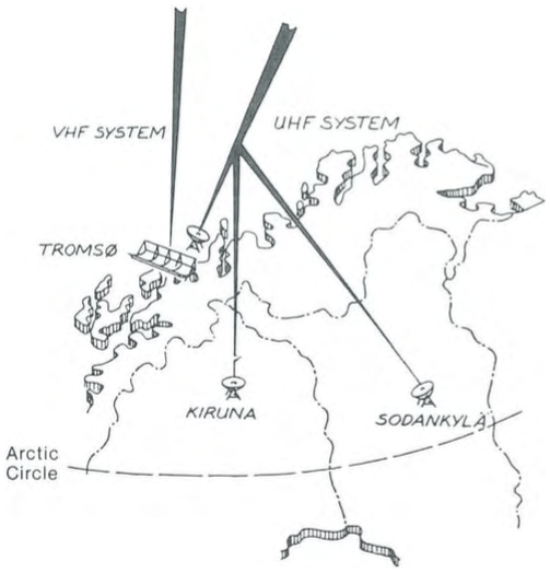
Figure 2Outline map of the EISCAT KST geographical area (from the 1984 EISCAT Annual Report). The initial road connection between the Tromsø site and the remote sites entered Finland at Kilpisjärvi, close to Treriksröset, the point where the Swedish, Finnish and Norwegian borders meet. From there it continued southward on the Finnish side of the Swedish–Finnish border. The connection to Kiruna branched off and crossed the border at Karesuando, about 110 km from Treriksröset, and the road to Sodankylä branched off at Muonio, 80 km farther on.
Another factor affecting travel between the sites was the customs control at the borders. Until Finland and Sweden joined the EU on 1 January 1995, and free mobility of goods throughout the EU was established, transport of goods between the three host countries was strictly controlled. This put an extra burden on the staff when preparing for a trip because all instruments, test equipment, tools and spare parts transported between the sites were considered merchandise and had to be declared; even the data tapes recorded in Tromsø and Sodankylä that had to be physically transported to Kiruna for processing at HQ were regarded as a sellable commodity! Every border passage involved a stop for customs control, at which the driver was expected to hand in a set of customs declarations prepared before the trip and containing a detailed classification and evaluation of the goods transported. During the first few years, before the customs personnel had become comfortable with the EISCAT transports, the car could even be subjected to an inspection. On the return trip, the exercise had to be repeated to ensure that no goods that had been allowed into a country free of duty were left there; everything had to be brought back out. In addition, a language barrier existed at the Finnish border checkpoints in Karesuvanto and Kolari. The staff there spoke very little English and if something was unclear and there were questions asked, things could get a bit stressful. Luckily, one of the Kiruna site engineers spoke Finnish, so when major shipments across the Finnish border had to be made, he was often doing the driving.
Once Sweden and Finland had joined the EU, all controls at the Finnish–Swedish border disappeared overnight. A customs border still existed into Norway, but handling at the Riksgränsen and Kilpisjärvi checkpoints soon became quite streamlined.
Following the principle decision in 1990 by the Council, the association's governing body, to develop a Svalbard radar, considerable time and effort was spent on a series of feasibility studies. These eventually led to the formal decision at the end of 1992 to begin the construction, following a hardware-driven strategy. The plan was to do as much of the hardware development work as possible in-house, using the staff and expertise already available at the sites. Areas where this was possible and advantageous included the receivers, the signal processing systems and the low-level digital control systems. The work was divided up between the sites along the same lines of responsibility as drawn up at the start of the mainland system and maintained thereafter: the radar controllers were assigned to Tromsø, the analogue part of the receivers and the transmitter exciter to Kiruna and the receiver digital back end to Sodankylä. Programming of the digital signal processor VME boards and overall integration into a VME environment became the responsibility of the deputy director with lots of help from the Sodankylä site scientist. About one and one-half position at each site, and a sizable fraction of the deputy director's work time, were tied up in this development work for nearly 4 years. The involvement of Tromsø staff gradually increased, particularly related to electrical power and transmitter installation work – the site mechanic worked on-site at the ESR for long periods – and for some time the mainland operation had to be restricted due to a resulting shortage of resources. But the end result was an indisputable success – the ESR saw first light on 16 March 1996, on schedule and within budget! It has operated reliably ever since. The technical details of the ESR project and the very first results are published elsewhere (Wannberg et al., 1997).
Once the ESR had stabilised, and manpower and capital investments into the mainland systems could be contemplated again, in 2002 the old ADC/correlator systems were scrapped and replaced with new digital back ends, patterned on the ESR signal processing system but using embedded UNIX computers for the correlation computations instead of DSP chips and including new ESR-type radar controllers. The resulting performance improvement was dramatic, allowing for the use of new and complex modulation schemes on both the VHF and the UHF, generally improving the rate of statistics and minimising the digital noise level and failure rate.
Many individuals working at the sites had few occasions to travel on the job and so not much opportunity to get to know their colleagues at the other sites and learn about their work first-hand. To help team building and to strengthen the team spirit, a review meeting of the whole staff was therefore held every year. This was a 3 sometimes 4 d combined work and socialising event, at which everybody had an opportunity to present their work in conference-format sessions and contribute to plans for the upcoming year in working groups, but the schedule also contained plenty of time for skiing, fun and play. The venue rotated between Finland, Norway and Sweden in a 3-year cycle. Local arrangements were as far as possible handled by the staff of the host country site, with help from HQ as needed.
During the first decade, the meeting was always arranged during the best skiing season in mid-March, when the sun had returned and the snow still lay metre-deep, at a resort not too far away from the local site and if possible with alpine slopes nearby, for example, Levi in Finland and Riksgränsen in Sweden. In later years, the meeting was often held in early autumn. In 2000, the meeting was held on board a Hurtigruten ship during its regular scheduled trip from Tromsø to Vardø and back, with an excursion to the North Cape included as part of the social programme.
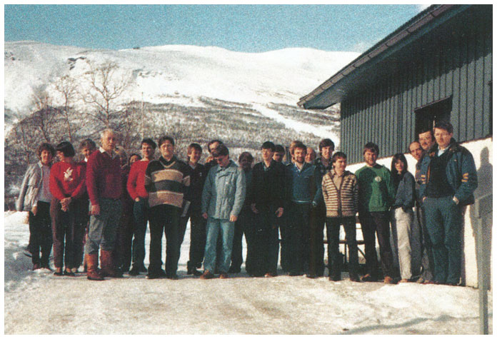
Figure 3Group photo of the EISCAT staff at the 1985 annual review meeting in Abisko, Sweden. Most of those pictured here have long since left the association and/or are now retired, but one individual is still working for EISCAT! From the 1985 EISCAT Annual Report.
On the last night there was always a banquet with lots of good food, a few speeches and a small ceremony where new team members were welcomed into the EISCAT family and old staff members acknowledged through the awarding of pins for 2, 5 or 10 years of service.
Proceedings were compiled after each review meeting and distributed internally. They frequently contained highly detailed technical material, served as very useful handbooks and reference material for the staff and were often referenced in the annual reports. They could be of great historical interest but unfortunately do not seem to have been saved in digitised form, at least not yet.
The annual Christmas parties were highly appreciated social events. They were arranged locally at the three workplaces, in Kiruna jointly between HQ and the site, a couple of weeks before the holidays, and took the form of a lunch or a dinner with lots of traditional Christmas food in a cosy local restaurant, followed by relaxed socialising by the fireside. Spouses were also invited.
For legal purposes, the EISCAT Association was established as a Swedish not-for-profit foundation (stiftelse) with its seat in Kiruna. Its executive branch, headquarters, also came to reside there.
A skeleton headquarters (HQ) was formed in 1976, establishing itself in office space rented from the Swedish Institute of Space Physics, IRF. HQ was in many ways organised along the same lines as the executive body of a typical mid-size company. The director, the top official, was the “EISCAT CEO”. He was appointed by the association's governing body, the Council, and responsible for implementing the scientific programme as defined by the Council and committees. He was also charged with maintaining relations with the local bodies in Norway, Sweden and Finland hosting the EISCAT sites. His staff included an assistant director science (ADS), responsible for the scientific operations, particularly the Common Programmes, and reporting to the Scientific Advisory Committee (SAC), an assistant director technique (ADT), responsible for the technical infrastructure, a business manager, handling the association's financial and business operations and communicating with the Administrative and Finance Committee (AFC), and a secretary. One or two administrative assistants (the number varied over time) were also employed. A very important part of HQ was the computer/software section. It was led by a head programmer, responsible for directing and overseeing the development and implementation of the software required to control the radar system, run experiments and record the data. The software section also handled the archiving of data, production of data copies and distribution of these to the users.
For the first years, work at HQ focussed on the actual establishment and construction of the radar system. The development, installation and commissioning of the antennas and transmitters were contracted out to industry. Monitoring and guiding the orderly progress of these contracts took up much of the director's time. Since most of the heavy equipment was being installed at the Tromsø site, the ADT was permanently stationed there until the end of the build-up phase.
At the same time, development of the application-specific software required to control the radar and the implementation of the Common Programmes was addressed by the association's own staff – a logical move, since the EISCAT system was the first of its kind, and no comparable installation using Norsk Data computers existed (see Sect. 10). In this work, the head programmer and his group were supported by the site programmers, each taking charge of a subset of the system and application software. The task of designing and realising the initial Common Programmes largely fell to the ADS, supported by expert users from the member countries, notably France and the United Kingdom.
In an attempt to keep own staff and eagerly waiting ionospheric scientists in the member countries up to date on the progress, a very ambitious EISCAT Newsletter was launched under the editorship of the ADS. Unfortunately, it seems that the workload at HQ soon overwhelmed the staff, and the newsletter just stopped. Very few copies are known to remain. I have a copy of no. 3, which is full of great information about the radar system and complementary instruments, like the STARE radar and the GEOS II and ISIS-2 satellites. It was probably the last issue.
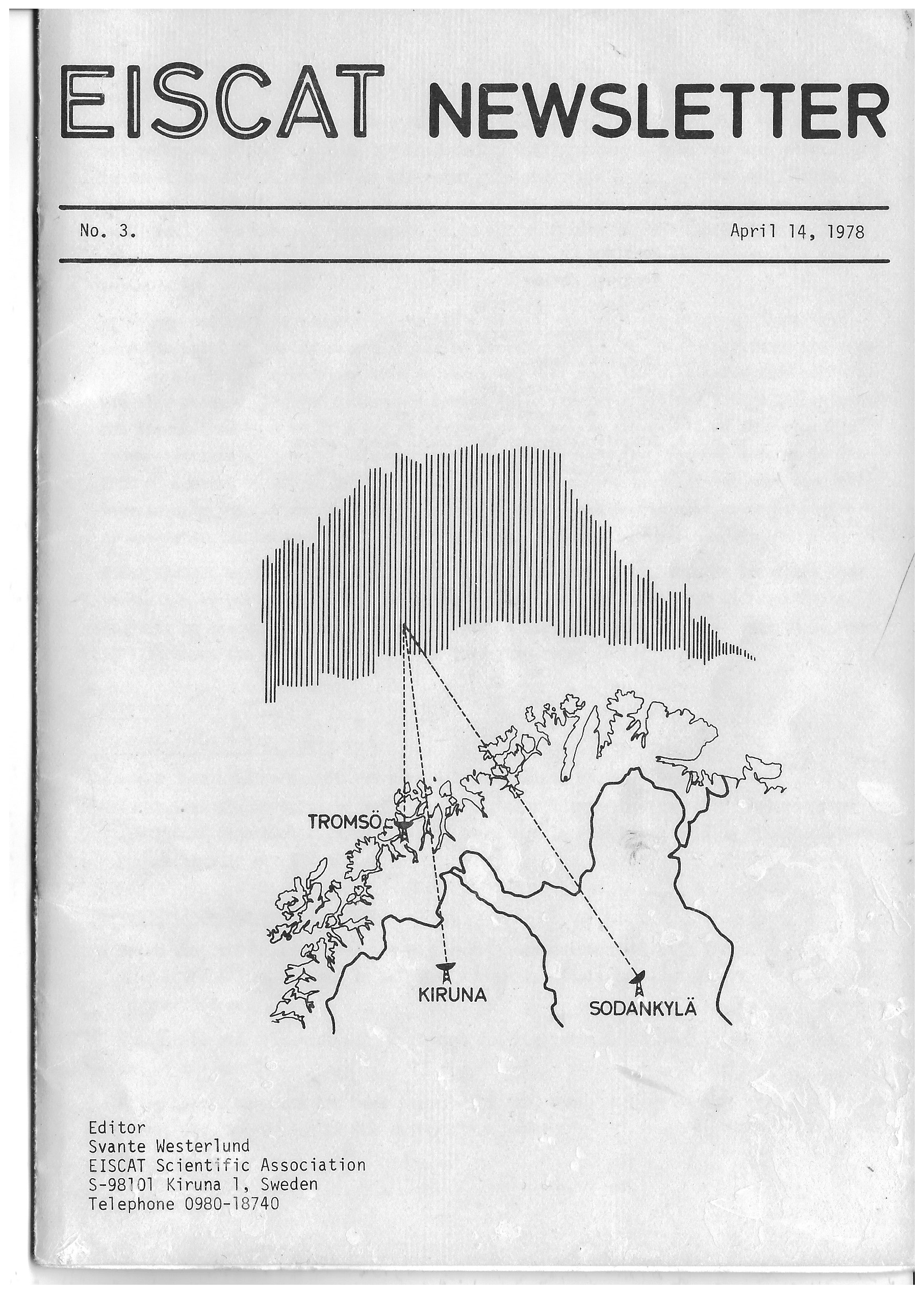
Figure 4Front page of the EISCAT newsletter, no. 3, issued by HQ in April 1978. Scan of my personal copy.
I had the opportunity to work under the association's first four directors, whose terms span the scope of the present paper. Looking back, it is clear that each of them was uniquely equipped to handle the tasks that dominated their respective time in office. As the first director, Tor Hagfors led the build-up phase. It would have been impossible to find a better qualified candidate. Hagfors was a brilliant theoretician and one of a small group of people who had derived the theory of incoherent scatter independently of each other. He also had extensive experience in science administration; before starting with EISCAT in 1975, he had served as the director of the Jicamarca and Arecibo radar observatories.
In 1982 Hagfors left for new challenges in the United States and was succeeded by Murray Baron, a radar scientist from SRI International in Menlo Park, California. Baron had a long career in ionospheric radar and had been deeply involved in the design, implementation and exploitation of the Chatanika, Alaska, ISR system. At this point in time, HQ was working on solving the VHF transmitter issue; Aydin, the California-based company contracted to build the transmitter, was in difficulties and lagging seriously behind the delivery schedule (see Sect. 9). Coming from a workplace located in the same high-tech area and with an intimate knowledge of US law and business practice, Baron was the ideal person to resolve the issue. Under his guidance, the VHF transmitter was finally delivered in 1984, and all remaining business dealings with Aydin terminated.
In 1985 the director's chair was filled by Jürgen Röttger of MPI Lindau. Röttger had a solid background in middle atmosphere physics and MST (mesosphere–stratosphere–troposphere) radar. He was no newcomer to EISCAT – he had already served as ADS under Baron between 1982 and 1984 and then left for a short stay at Arecibo, from where he was recalled. He took over an EISCAT that had started to function reasonably well and led it through an extremely productive period, including the design and construction phase of the Svalbard radar (ESR) project and culminating in the commissioning and inauguration of the ESR in 1996. He was an extremely committed leader, who took a deep personal interest in almost all aspects of the association's work and eventually came to be the longest serving Director, leaving in 1997 after 11 years in position. His personal scientific interests manifested themselves in an increased emphasis on the development and operation of experiments optimised for mesosphere observations, with the long series of observations of polar mesospheric summer echoes (PMSEs) perhaps the most important contribution.
History then repeated itself – Röttger was succeeded as director by Tauno Turunen, who had been ADS from 1984 to 1987 and devised, programmed and tested the series of GEN programmes that came to be templates for nearly all EISCAT experiments for more than 10 years. Turunen's professional affiliation was with the Sodankylä Geophysical Observatory. He was primarily a hardware man with a background in ionosonde technology and radar coding and had been involved with the initial setting up of the Sodankylä UHF site. He had also served on different committees in an expert capacity. During his time as director, he oversaw the completion of the ESR 42 m antenna project and supervised a major rehabilitation of the mainland systems, which out of necessity had not been fully maintained during the ESR build-up phase. He also continued his experiment design work, making full use of the new signal processing capabilities introduced as part of this process.
When the IRF in 1999 began a major rebuilding project, the wing containing the HQ offices was targeted for demolition. After a crash investigation of different alternatives, the whole HQ operation moved into rented office spaces in the town centre of Kiruna, where it remained until 2007. Turunen thus came to spend most of his term in these new surroundings. He left EISCAT in 2002 and was succeeded by Tony van Eyken, who had been selected to lead the association into what could perhaps be termed the “Svalbard radar harvest season”. But that is a different story, which is not addressed here.
Looking back through the earliest documentation, it is obvious that the steering group was convinced of the feasibility of the UHF system very early on through contacts to industry and already operating ISR systems. The Yellow Book contains a highly technical description of the proposed transmitter, based on a feasibility study for the St. Santin radar and complemented by a detailed costing; the actual transmitter was largely patterned on this proposal. A detailed description of the antenna and receiver system planned at the time is also presented there, but this was of course superseded by the later decision to go for fully steerable antennas at all sites.
The UHF transmitter actually did perform largely as planned already from the start and soon evolved to a point where the hardware was regarded as predictable and reliable. It was planned as a two klystron system, but initially only one tube was installed. It was then run with just one klystron until the output power of the second of the two original VA862 Varian klystrons started to drop.
The VA862 design was special in that it allowed for the transmission of very long pulses of up to 10 ms duration. This was the result of deliberations in the planning stage, when it was believed that quasi-continuous-wave (CW) illumination of the beam intersection volume would be required to get acceptable velocity statistics at the remote stations. But by 1982, data from CP-0-type experiments clearly demonstrated that good velocity estimates could be had using a common ≈ 350 µs pulse for all sites, so the long-pulse capability was never put to serious use, and when performance requirements for new klystrons were drafted, the maximum pulse length was set at 2 ms. A proposal by the Thomson corporation for a klystron with better efficiency than the old Varian tubes was accepted, and an order for two tubes was placed. Since the transmitter oil tank and much of the waveguide were already prepared to accept two tubes, both new klystrons were installed upon delivery and have since been run in parallel for a typical output power in the order of 2 MW; 3 MW was theoretically possible but rarely achieved because of high reflected power limitations.
It was well understood that the UHF signals backscattered from the ionosphere would be very weak much of the time. The cosmic noise background would not be a problem – at 933 MHz the sky noise temperature is typically 10–15 K – but in the receiver, the signals would have to compete with noise generated in the first amplifier stage, typically 10 to 100 times stronger than the signal, resulting in signal-to-noise ratios of only a few percent. A prime design target for the UHF receiver was therefore the lowest possible noise temperature. It was clear that to reach the remote station target system noise temperature of ≈ 30 K, a cooled receiver front end would be mandatory. On advice from the radio astronomy community, the designers chose a solution based on a wideband, high gain, cryogenically cooled parametric amplifier, designed and built by AIL of Long Island, United States. This device could deliver about 60 dB of gain over a 30 MHz wide band while adding less than 20 K to the overall system noise. Unfortunately, it also turned out to be extremely sensitive to overload and ill-suited for use in a radar system. At Ramfjordmoen, klystron arcs resulted in several burnt-out amplifier upconverters. These could not be repaired locally but had to be shipped back to AIL, causing major disruptions of the schedule. To maintain operation, the Tromsø system had to rely on uncooled transistor amplifiers with much poorer noise performance. These were eventually replaced by GaAsFET amplifiers designed and built at the Kiruna site, which brought the system noise down to 90–100 K. At the remote sites, the paramps were kept in operation for several years, but when the first mobile phone base stations started up in Kiruna and Sodankylä, their wide passband proved to be a liability; they went into saturation and had to be replaced by an in-house designed cooled GaAsFET amplifier system. The cryosystems were maintenance intensive and occupied a lot of the responsible engineer's work time.
Another shortcoming of the initial receiver design manifested itself very quickly after the start of regular operations. The original post-detection filters, located immediately ahead of the ADC, had been designed with insufficient regard to the need for phase linearity and were also plagued with DC offset problems. Following a critical report from a study group led by Turunen (Turunen et al., 1981), new filters were designed based on experience from the Sodankylä ionosonde and featuring optimised impulse response for all commonly used pulse lengths. Such filters were then produced at the Sodankylä site in sufficient numbers to allow for a system-wide refit of all receivers.
The 32 m UHF antennas (Fig. 3) were “wheel-on-track” Cassegrain designs, based on a standard Intelsat-1A ground segment antenna design that had already been built in substantial numbers but with modified feed systems to adapt them to work at 933 MHz. The alidade (i.e. the moving structure carrying the reflector) stood on four wheels that rode on a circular track on top of the antenna foundation. Two of the wheels were fitted with DC motors that drove the antenna in the azimuth plane. A further two motors, located on a platform level with the elevation axis, drove the reflector in the elevation plane via a massive tooth rack.
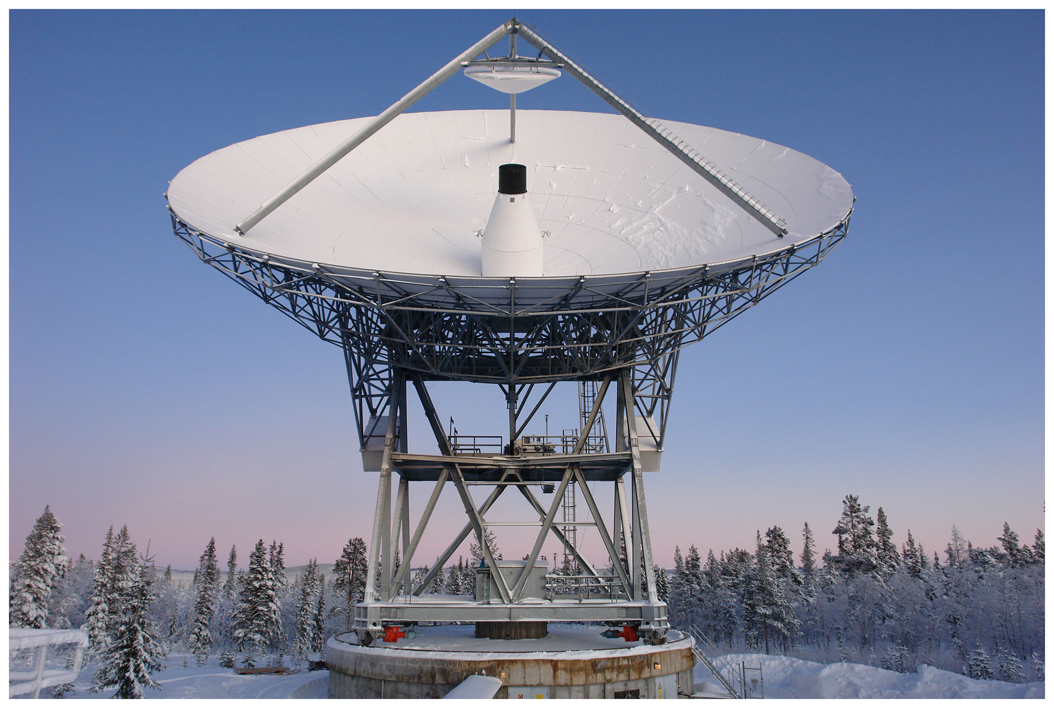
Figure 5The Kiruna EISCAT UHF antenna. The Tromsø and Sodankylä antennas were identical, apart from the feed system of the Tromsø one, that included a waveguide run with rotary joints connecting to the transmitter. Photo courtesy of Lars-Göran Vanhainen, Swedish Institute of Space Physics (IRF).
In the Intelsat application for which the antennas were originally designed, fast movement was not needed, as the antennas were used as the ground endpoints of links to geostationary communications satellites and therefore only needed to move slowly to optimise the pointing to the satellite or to move to a stow position. The EISCAT application was quite different; an ability to move rapidly was essential for many observations, and so the drive motors and gearboxes fitted to the EISCAT antennas were much more powerful than those of the ancestor antennas. It soon became obvious that this mode of operation also resulted in a much increased need for regular service of the drives and the antenna structures.
Lubrication and routine maintenance of the drive systems was carried out by the local site staff. They also looked after the “pintle bearing” that kept the antenna centred on the rails. A number of plastic-coated segments, mounted on a ≈ 2 m diameter concrete cylinder centred on the azimuth axis, made up the fixed part of this bearing; the moving part consisted of four pads bolted to the alidade. The fixed pads wore out quite fast and had to be replaced about once a year on average, but soon an efficient routine evolved; worn-out pads were sent to Finland and reconditioned there by a company specialising in industrial plastics.
Major maintenance work required calling in outside help. The alidade and the reflector backing were bolted together, and the bolts required regular re-tensioning at a few years' intervals, a job requiring a crew certified for climbing and high-altitude work – the top of the reflector backing was 35 m above ground! This job was therefore always contracted out. It was normally scheduled for a period of low demand in the summer and combined with a general overhaul of the reflector. To minimise the impact on the regular operation, all three UHF antennas were serviced one after the other in this manner during a single summer season whenever possible.
Bolt tensioning could be planned for in advance, but the same was not always true of the rail maintenance. After about a decade of operation, it was discovered at all three sites that the concrete carrying the rails had started to fracture in places, and the rails were settling and even coming loose. This was a serious condition that had to be addressed promptly whenever detected, irrespective of season or weather: the antenna had to be locked in azimuth, the fracturing concrete chiselled away from underneath the rail and new frost-proof, rapid-curing concrete poured in, while monitoring that the section under repair ended up level with the rest of the rail. This work was always performed by contractors but closely monitored by the site staff to ensure correct rail alignment.
For some time, the safety of the Finnish UHF antenna, located at the Tähtelä observatory about 10 km south of the town of Sodankylä, was in question due to actions by entities outside EISCAT control. This antenna stands on sandy soil just 80 m from the east bank of the Kitinen River. When the association was established, the river and its tributaries were still unregulated, but in 1988, Kemijoki OY, the company possessing the water rights, applied for a permit to construct a hydropower plant at Kurkiaska, about 3 km downstream from the observatory. This involved damming the river and raising the water level by about 6 m, so creating a water reservoir stretching tens of kilometres upstream from the dam. As soon as EISCAT got to know about the project, a strong statement of dissent was submitted to the water rights court; if the river were allowed to rise to the level requested in the project plan, the ground water table at the antenna would rise to almost 2 m above the foundation footplate! This would introduce a risk for frost heave and in the worst case endanger the long-term stability and operability of the antenna.
Geotechnical experts were called in to consult both parties and long negotiations ensued. In the end Kemijoki OY agreed to a damming limit nearly 3 m lower than first planned for, which ensured that the ground water table at the antenna would always be at least a metre below the bottom of the foundation. The company also agreed to put in insulation and a heating cable all around the foundation to protect against frost heave and to cover the operating costs of the heater for the lifetime of EISCAT. This agreement was made legally binding on Kemijoki OY by a decision in the water rights court on 29 December 1988. The heater and the insulation were put in the next summer. No problems related to the damming have been noticed since.
The 1971 feasibility study (the Green Book) put forth strong arguments for a VHF system. Foremost among these was the ability to make measurements in conditions of very low electron density, in the mesosphere and the bottom of the E layer and in the topside ionosphere at altitudes well above 1000 km, where it was expected that it would detect the theoretically predicted “polar wind”. The Green Book only contained a rough outline of the envisaged system, but the concept soon matured into a very ambitious design, comprising a 5 MW dual klystron transmitter, a 120×40 m parabolic trough antenna (Fig. 4), steerable in the meridian plane between 30∘ N–60∘ S, and a high-power RF switchyard, enabling operation in two distinct modes (Mode 1 and Mode 2). An overview of the system as first implemented is given in Baron (1986), but a recapitulation of its most important features is included below as a background to the long, costly and frustrating series of mishaps described in the following.
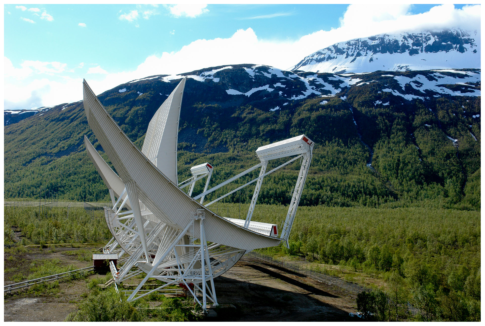
Figure 6The EISCAT VHF parabolic cylinder antenna at Tromsø. It is constructed as four individually tiltable 30×40 m reflector–feedline segments, which however must be electrically operated either as a single 120×40 m aperture (Mode 1) or as two independent 60×40 m apertures (Mode 2). Photo courtesy of Lars-Göran Vanhainen, Swedish Institute of Space Physics (IRF).
Mode 1 was optimised for maximum sensitivity. One klystron would drive all 128 horizontal dipoles in the antenna feed, and the other klystron would drive all 128 vertical dipoles, making it possible to transmit either linearly or circularly polarised signals and to change the polarisation on a pulse-by-pulse basis. With separate receiver chains for the two sets of dipoles, both total signal power and spectrum and Faraday rotation phase as functions of range could be recovered. In Mode 2, the antenna would be electrically split into two 60×40 m “half antennas”, configured for circular polarisation and fed by one klystron each. The two antenna halves could then be independently pointed in different directions both in elevation and in azimuth, effectively creating a dual beam system at the expense of sensitivity. However, for either mode to work as intended, there had to be two working klystrons in the transmitter, and precisely this turned out to be easier said than done.
On 2 March 1976, EISCAT placed a contract for its transmitters with the California-based Aydin Corporation. This was to be a turnkey deal, with Aydin handing over a fully working transmitter system by November 1978. At the time, no high-power klystron manufacturer could demonstrate a tube meeting the EISCAT requirements, but Varian associates of Palo Alto offered to develop a 224 MHz, 3 MW tube by extrapolating from a design for a slightly different frequency. This was accepted, an order for three klystrons was placed and after construction and ageing at Varian these were delivered directly to Aydin for integration in the partially completed VHF transmitter.
But from then on, things did not progress smoothly. At the end of 1982, Aydin had fallen behind the project plan by almost 3 years, two of the Varian klystrons had failed during testing and the third was performing well below agreed specifications. The transmitter was finally delivered to Tromsø in 1984, and following this the contract with Aydin was terminated.
In parallel, EISCAT had started searching for an alternative klystron supplier. In 1983, the Valvo division of Philips was contracted to supply two klystrons with better specifications than the original Varian tubes. Delivery of the first Valvo tube, YK1320/1, was planned for December 1984 but slipped into early 1986, which allowed it to be immediately installed in the VHF transmitter; this had by then been operated at up to 2.5 MW with the only remaining Varian klystron.
The Valvo tube worked but did not meet the performance requirements. It could be operated at 90 kV beam voltage, delivering about half of the contracted output power, 1.2 MW, but on raising the beam voltage further, it started arcing; not even a 300 h ageing process improved this behaviour. Tore Wessel-Berg of NTH and Jim Tallmadge of SRI International, both high-power klystron experts, were called in to evaluate the situation in collaboration with the Valvo engineering team. After a thorough analysis, it was concluded that the tube design was basically sound, but a number of modifications were required to make it operate stably at full power, all of which would require the tube to be returned to Valvo for rebuilding. The proposed modifications could be directly incorporated into the second klystron, still under production at the Valvo plant. Left with no alternative, the Council resolved to let Valvo modify the klystron according to the expert group recommendations.
Meanwhile, at the end of 1986, the Tromsø site staff succeeded in running the system with both klystrons (the Valvo and the Varian), albeit at very low power. The full antenna was now used in experiments for the first time, and very strong, spectrally narrow returns (later termed PMSEs) were received from the mesosphere, which was quite unexpected. Extremely interesting diagnostic data from a heating campaign were also recorded. These results demonstrated that the system was indeed capable of meeting several of its intended scientific targets.
When I started as ADT in July 1987, my first task was to take charge of the VHF commissioning. Progress was continually held up by problems: the Valvo klystron developed a vacuum leak, water leaks flooded part of the transmitter, ruining several focussing solenoids, and the last remaining Varian klystron failed irreparably. But the second, modified Valvo tube, which arrived in August, showed promise; it could be operated at up to 2.5 MW at better than 45 % efficiency, a major improvement on the Varian tube. On the other hand, the contractual demand that the Valvo tubes had to be mechanically compatible with the Varian ones had forced Valvo to make the beam collector quite small, so it could not dissipate the full ≈ 600 kW beam power with no RF drive present, which the Varian tube could do. To prevent a catastrophic collector meltdown, several levels of protection had to be introduced before Valvo would release the tube for experiment operation. To that end, software safeguards were incorporated into the TARLAN compiler, and a microprocessor-based collector dissipation monitoring system was constructed by Tromsø site staff.
Confidence in the klystron-based system was now rapidly evaporating, so in 1989, HQ initiated a feasibility study to consider the replacement of the transmitter by a power-grid-tube-based system. Companies active in the broadcast and particle accelerator segments were approached, on-site meetings with technical representatives were held and HQ staff visited several accelerator facilities using megawatt-class gridded tubes. Impressions were positive, and the concept was seriously considered for a while. However, when the first Valvo tube was returned to Tromsø in 1990 after rebuilding, limited dual klystron operation became possible again, and the transmitter replacement programme was put on indefinite hold. But before long, new klystron problems arose that led to a second rebuild of tube YK1320/2, a number of costly consultancy visits from SRI and the full-time involvement of two–three site staff for nearly a year. It was only in late 1991, 10 years after the inauguration, that the VHF transmitter started to behave somewhat reliably, and to achieve this, the Faraday rotation capability first had to be given up due to frequent malfunctioning of the duplexers and receiver protectors.
With two functioning klystrons, the system could now be run in both modes. Mode 2 was put to good use in experiments designed for measuring the ionospheric convection velocity field over a wide area to the north of Tromsø. With the VHF antenna pointed to its lowest elevation, 30∘, and phased to generate two beams, one due north and the other approximately normal to the L shells, Doppler velocities could be derived for a series of range gates along both beams and combined to generate two components of the 3D velocity. The third (semi-vertical) component could be provided by the UHF for the close-in ranges, out to some 300 km north of Tromsø, but farther towards the north, it had to be extrapolated or was assumed close to zero. Variants of this experiment were used as core parts of Common Programme 4. When the Svalbard radar came on the air in 1996, it was often run together with CP 4 experiments, pointing southward into a region where the fields of view of the two systems overlapped; under favourable conditions, the full 3D velocity field could be determined over a large area in this way. Mode 1 suffered from a serious operational restriction: with the antenna pointing in the field-aligned direction and the transmitter operating at full power, radiation spillover from the upper edge of the antenna reflector was so strong that the Norwegian limits for public exposure to non-ionising radiation (which had been lowered since the antenna was designed) were exceeded even a kilometre to the south of the site. Four private homes along the main road suffered from bad interference to telephones, TV sets and audio equipment, and Tromsø site staff had to spend lots of time and effort on installing shielding, filtering and better TV antennas. A number of mitigation schemes were investigated, for example, extending the main reflector, tilting the feeder bridge or erecting a 50 m high fence immediately south of the antenna, but all proved too complicated and costly. In the end, full-power operation with the beam directed to the south of vertical had to be given up. This effectively eliminated one of the hoped-for core capabilities of the VHF system, regular high-altitude field-aligned observations vital to the hunt for the polar wind. Single-beam high-altitude VHF operation thus became limited to vertical and has remained so until today.
In the late 1980s, scientists at the Russian Polar Geophysical Institute (PGI) obtained funding for a receiving site for the EISCAT VHF transmissions to be built at Verkhnetolomsky on the Kola Peninsula, about 510 km ESE from the Tromsø site. A large phased array, comprising eight 50×50 m 64-element modules and a matching dual polarisation receiver, handling both Mode 1 and Mode 2 transmissions, was to be constructed. The system was partially completed by 1991, and preliminary results were presented at the fifth EISCAT workshop (Khudukon et al., 1990).
The PGI initiative was seen as a potentially valuable complement to the VHF system, so a number of tests were carried out, with the VHF transmitting long pulses vertically and the PGI system receiving. However, no signals were unambiguously identified. Time synchronisation remained a possible uncertainty, so a so-called TV sync receiver was prepared by the Kiruna staff and shipped to the PGI group. Unfortunately, this did not solve the problem. After a couple of years the PGI group dispersed, and their fine system was left unfinished. Multistatic VHF observations thus had to wait until 2012, when the Kiruna and Sodankylä dishes were converted to VHF, after the introduction of UMTS mobile phone systems had made continued UHF operations impossible. At about the same time, the Finnish KAIRA phased-array receiver system at Kilpisjärvi (McKay-Bukowski et al., 2015) also successfully started to receive the VHF transmissions, providing an additional baseline and multi-beam capabilities.
11.1 The Norsk Data computers
In the early 1970s, a European big science project many times larger and more complex than EISCAT was already nearing completion. In 1971, the CERN Super Proton Synchrotron (SPS) project had finally got underway after years of financial negotiations, with the goal of constructing a 300 GeV accelerator at a total cost of up to 1150 million y1971 Swiss francs, more than 30 times the projected y1974 cost of the EISCAT UHF system. To the dismay in some quarters and considerable scepticism among competing computer manufacturers, the Norsk Data Nord-10 minicomputer had been selected as the main control computer for the new accelerator, based on the proven reliability of its predecessor, the Nord-1, and its real-time-geared architecture. At the request of CERN, Norsk Data had provided the Nord-10 machines with a special input–output channel dedicated to communicating with CAMAC, the de facto standard for fast nuclear and particle physics electronics widely used at CERN. By 1976, a total of 25 Nord-10s were already in operation at different points around the newly commissioned accelerator ring.
All this was noted with interest by the EISCAT planners. Many of the processing demands of the radar system, including the need for fast and predictable interrupt response, were similar to those of the CERN SPS, and the possibility to use CAMAC modules to connect all project-specific hardware to the computers was regarded as extremely valuable. Also, the fact that CERN had already committed to the Nord-10 and would have to maintain its machine complement for the foreseeable future guaranteed that support for the Nord-10 would remain available during the planned time span of the EISCAT project. Discussions with Norsk Data AS were therefore started, leading to an order for five Nord-10 systems, two for Tromsø, one each for Kiruna and Sodankylä and the fifth to be part financed by the IRF. This machine was to be located in the IRF computer centre, shared between HQ and the IRF EISCAT group and used both for software development and for data tape copying.
As delivered, the Nord-10 machines were equipped with 128 kB of RAM. This was enough to get started but soon proved too little and was expanded to 256 kB. CDC Hawk cartridge disk drives, each drive the size of a small refrigerator, provided random access storage; removable and interchangeable disk cartridges stored 5 MB each. Data recording was on reel-to-reel in., 9-track magnetic tape at 1600 Bd in.−1. The Tromsø site computer had two tape stations, one each for Kiruna and Sodankylä. The largest tape reels that could be fitted were 10.5 in. (27 cm) diameter and contained about 2400 ft (731 m) of tape, corresponding to ≈ 46 MB of data. To put this in perspective, a USB memory stick can offer upwards of half a gigabyte of random-accessible storage in a cm package. There was also one graphics display at each site, a Tektronix monochrome unit displaying the autocorrelations computed from the raw data, using the program RTGRAPH.
Anyone born in the 1990s or later will probably regard it as almost unbelievable that anything useful could be accomplished in this extremely restricted computing environment – but the Nord-10s successfully ran the UHF system for the first 5 years! However, already early on, it became obvious that they were not fully up to the demands raised by the quickly expanding operations. As a temporary help, in 1984, the RAM was expanded to 512 kB, using EISCAT-designed memory banks. Concurrently with this, Norsk Data were introducing more powerful processing units, and in 1986, all Nord-10s were replaced by ND-530/CX systems with 2.5 MB of RAM memory and vastly increased hard disk capacity.
11.2 EROS and TARLAN
The last Nord-10 machine was delivered in late 1977, and at that point software development started in earnest. The plan was to make the complex radar system user-friendly and easy to use. Under the direction of the HQ head programmer, the software staff at HQ and the sites now set out to develop an integrated software environment, following a basic concept developed already before the first computers were delivered. This came to be known as EROS, the EISCAT Real-time Operating System. A crucial step was the construction of the command language, ELAN, whose structure and syntax were patterned on SINTRAN, the Nord-10 operating system. Most of the EROS software was written in Norsk Data's own Fortran dialect, ND-Fortran.
Operator interaction with the EROS system was through ELAN commands, issued through a simple line-oriented user interface running on an alphanumeric terminal. This provided access to all major hardware, mechanisms to call up and run predefined experiments from file and the ability to interact asynchronously with a running experiment – possible because ELAN was an interpreted language. Below the user interface level, a large number of device-specific and mutually interacting programs and device drivers handled individual subsystems through CAMAC. EROS was quasi-real-time-capable; the execution of commands could be scheduled to occur at specified points in time to a resolution of 1 s, and there was a catch-up facility that enabled crashed and restarted experiments to seamlessly get back in sync with the other sites. Inter-site communication was arranged via leased telephone lines and made an integral part of EROS; it was possible to access the systems at the other sites, send messages, check hardware and data taking status and even command the antennas and start and stop experiments. As the system stabilised, this functionality was gradually used to eliminate the need for all-night staffing of the remote sites during experiments; visiting scientists often came singly to Tromsø and ran their special experiment campaigns from there, relying on the remote command facility to handle the remotes and trusting them to behave – which they did most of the time.
While the design, development and evolution of the core EROS system and the data handling routines resided with the HQ software group, the development of driver software for most subsystems was assigned to the site programmers. The UHF antenna control routines, as well as an advanced system for antenna pointing calibration based on radio stars, were developed in Sodankylä. Kiruna developed drivers for the receivers and real-time clocks, and Tromsø managed the initial stages of radar controller and correlator software development in collaboration with individuals from the Nordlysobservatoriet and NTH Trondheim, notably Hans-Jørgen Alker.
The original EROS system was in more or less continual evolution for about 20 years, particularly with respect to the data collection and recording parts that had to keep up with the gradually increasing data volumes and the introduction of new storage media (fixed hard disks, Exabyte tape, etc.), taking up a considerable fraction of all programmers' time for years into the operations phase. Unfortunately, very little documentation of all this development work exists in accessible form today. Two important technical reports documenting the interfaces between EROS and EISCAT users have survived, one teaching the user how to programme the radar using ELAN (Armstrong, 1980) and another describing how to access the data (Farmer, 1980). This latter report shows that much thought went into defining recording formats simplifying end user access to the data, while at the same time adhering to established standards (ANSI X3.27 and British BS4732). As far as the inner workings of EROS were concerned, it appears that the programming staff relied on the Fortran source code being self-documenting, and therefore no reports seem to have been produced; none were found in the 2020 EISCAT HQ major search and review of old documentation.
While EROS and its component parts thus controlled most of the radar system, two critical subsystems were handled individually: the radar controller (RC) and the correlator. The RC generated the signals controlling the transmitter, ADCs and Correlator during a radar cycle; the Correlator was an application-specific, pipelined device that processed the received data on the fly. Both were operating at microsecond or sub-microsecond time resolution, had to be programmed at the bit level and were best left alone once started and running. For these reasons, two unique languages, TARLAN and CORLAN, were constructed. Both were compiled – the logical design choice for languages constructed to control units with the ability to cause unpredictable and even dangerous system behaviour if handled randomly.
TARLAN was the Transmit And Receive LANguage for the RC. It had a simple syntax – individual hardware devices were addressed by symbolic names, and the time when an operation was to be performed was given as the number of microseconds after the start of a cycle. All commands had to be in time sequence, and transmitter commands had to be issued in a specific order and with certain minimum time separation to ensure a stable output waveform. Formally correct TARLAN code was translated by the compiler into a bit-level file, which could be loaded into the RC. Whether the code made the radar do what the experimenter was hoping for then had to be checked in a test run.
The history and specifics of CORLAN are tightly interrelated with the Correlator hardware design and therefore treated in the Signal processing section.
11.3 Data handling
The end product of all EISCAT operations was the “raw data”, the time-averaged autocorrelation data output by the correlator, complemented by metadata describing the system status (transmitter power, frequency, antenna pointings, etc.). For the first few years, the extremely limited hard disk space forced a solution where raw data dumps were continually written to tape during experiments. Most experiments dumped data every 10 s. In Tromsø, a large tape then lasted at least 15–16 h if the experiment did not crash (a crash often led to a forced tape change and a restart), but experiments running over several days involved a number of tape changes, often during the night shifts. The data volume at the remotes was much smaller, as only some three signal-carrying range gates, centred on the beam intersection point, were computed.
Initially, it had been estimated that the Tromsø system would generate in the order of 100 data tapes per year, but as experiment operations picked up and new coding schemes were introduced, the number of tapes grew dramatically. As a result, tape handling expanded into an almost full-time job. EISCAT was responsible for making archive copies of all data tapes and archiving them securely. In addition, user copies had to be made and forwarded to the data representatives in the member countries. Copies of Special Programme data collected during national experiments were only sent to the respective member country, whereas all Common Programme data had to be distributed to all member countries, requiring six copies. The copying and archiving job was centralised to HQ in Kiruna, so tapes had to be physically transported there as soon as convenient after an experiment. As shipments from Tromsø and Sodankylä always involved a trip by car, a routine soon developed where tapes were accumulated locally until the shipment could be combined with a visit by a staff member for some other purpose. Sometimes two, three or more boxfuls of tape were shipped at once, creating a massive peak in the workload at HQ. Eventually a part-time data assistant position with responsibility for all tape handling had to be created.
After a few years, user demand and the availability of more computing power in the form of the ND-530 machines led to the introduction of a near-real-time quick-look analysis program, which produced first-order estimates of standard parameters (plasma density, electron and ion temperatures and velocities) on the fly. These estimates were also saved and distributed to users. Following the installation of a ND-5400 machine in 1990, EISCAT HQ was connected to the Internet via the IRF and its connections to SUNET, the Swedish university network. From this time onwards, the physically small DAT and Exabyte tape formats were introduced as a replacement for the reel-to-reel tapes, and data transfer and distribution was gradually moved from physical media to file transfer over the net, eventually replacing the shipping of raw data tapes from the sites to HQ and putting an end to all shipping of tapes to the associates.
12.1 The Alker correlator
The ultimate purpose of an incoherent scatter radar observing the ionosphere is to determine the physical state of the scattering plasma: its electron and ion temperatures, ion composition and bulk velocity. Any particular combination of these parameters results in a corresponding distribution of scatterer (electron) velocities, which in turn manifests itself as a specific power frequency distribution of the scattered signal. After processing by the radar receiver, the signal is sampled at regular time intervals and digitised, such that the output from the ADC forms a discrete time series of signal complex amplitude estimates. A straightforward way to extract the desired information from the signal is now to compute time-averaged autocorrelation functions (ACFs) over segments of the sample stream. When EISCAT was in the planning stage, this time-domain approach was already used at the Chatanika radar, where two different digital correlators were in use, one hardwired for long pulse modulations and the other semi-programmable (by rewiring) for multipulse modulations. It was decided to follow this route also in EISCAT by employing the famous “Alker correlator”.
The Alker correlator promised to be a major improvement over the Chatanika units. It started as a doctorate thesis project at the Norwegian technical university in Trondheim (NTH), with design targets set by the envisaged requirements of the coming EISCAT system and (at least initially) supervised by Tor Hagfors. The result was a software-programmable device optimised for computing complex-valued correlation functions, potentially very flexible and in principle able to handle experiments combining several different types of modulation in each radar cycle. A detailed description of its pipelined architecture is given in Alker (1979). It was designed for a sustained multiply–accumulate rate of 5 MHz, using the latest state-of-the-art components, some of which were not even commercially available as the work started: AMD 2900 bit-slice processors, TRW LSI 8×8 bit multiplier chips and static NMOS chips making up the input and output memory banks. The program flow could be controlled by conditional jumping, based on the values of three programmable loop counters, which allowed for a degree of structured programming. Unfortunately, the program memory was only 63 instructions deep (it had to be very fast and was therefore expensive), which was a severe limitation on an otherwise beautifully thought-out design.
The first physical realisation of the correlator turned out to be marginal. It was constructed as two separate 19 in. rack-mounted units interconnected by flat cables, one containing the double-banked input memory and the other containing the arithmetic unit (the only part of that unit actually constructed on printed circuit boards) and all control logic. The signal ground provided by the flat-cable connection between the two units proved to be too weak for the 5 MHz data rate. The ADCs used 2's complement data coding, so signal voltage variations around zero volts caused all data bits on the bus to change from all zeros to all 1s or vice versa. Because of the weak ground, this created lots of common-mode digital noise on the bus, which partly corrupted the desired signal.
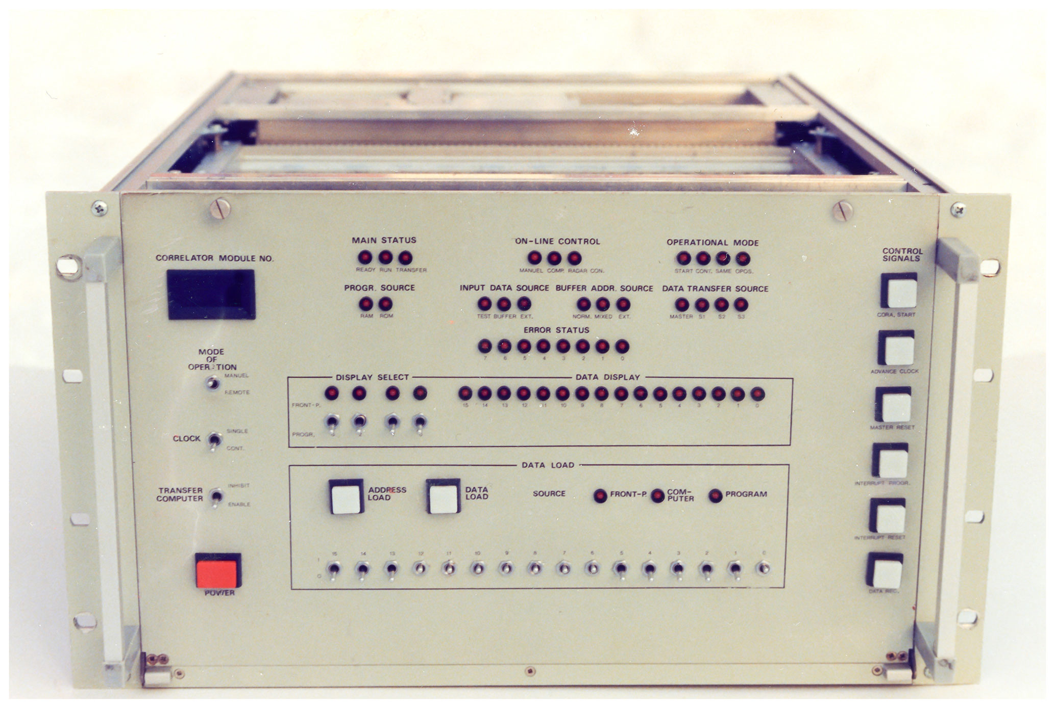
Figure 7The arithmetic unit of one of the Alker correlators. The front panel layout has many features reminiscent of minicomputers of the 1970s era, in particular the “data load” field with 16 switches to set up and manually load individual micro-instructions into arbitrary program memory locations; the front panel of the Nord-10 computer had an almost identical field for the same purpose. Photo courtesy of Lars-Göran Vanhainen.
Internally, both the buffer memory unit and the computing unit were constructed using wire-wrapping, a construction method extensively used for logic systems in the 1970s and 1980s, which has now largely disappeared. It was useful for producing prototypes or small series of non-standard systems, but when improperly applied it could produce all sorts of illogical malfunctions. Unfortunately, this was the case with the correlators. During the first year of operation, the Kiruna unit could now and then stop in the middle of an experiment and refuse to load and start, leaving the site staff with no option other than to start pulling circuit boards. After a while, we developed a very direct troubleshooting technique: the circuit boards were banged down on the kitchen table, wire-wrap side down. This often caused one or several pieces of overstretched and broken-off wrap wire to fall out of the wire mat; it then remained to locate the broken connection and put in a new wire!
This unsatisfactory state of affairs could have continued for quite some time, as there were only four correlators (three for the UHF system and one for the VHF), and the demand for experiment operations was increasing all the time, leaving no time for preventive maintenance. But in January 1983, a capacitor in the Kiruna correlator exploded and set fire to some internal cabling, spreading residue inside the unit and releasing acrid smoke that triggered the fire extinguishing system. I was there when it happened. Fortunately, all equipment was insured, and contact to the insurance company confirmed that the repair costs would be reimbursed in full. A rehabilitation programme was now started. All electronics in the receiver room was thoroughly cleaned to prevent corrosion from the hydrochloric acid fumes. At the same time, the VHF correlator was transferred from Tromsø to Kiruna to allow tristatic measurements to continue; we could do this as the VHF system had no transmitter at the time anyway. The burnt-out unit was totally stripped out and rebuilt from the ground up by EISCAT staff, using quality components and proper grounding techniques. Reliability improved dramatically; the correlator could now operate for weeks on end without stopping, and the common-mode noise in the data all but disappeared. The other correlators were then rebuilt in the same way, one by one. By late summer 1985 all four had been rebuilt. In the process, new result memory boards were constructed, doubling the result memory space to 4096 addresses. During 1986, a further improvement was introduced in the form of an internal 2×16 kiloword buffer memory. On a single circuit board, this provided twice the address space and all the functionality of the old buffer memory unit, which became redundant and was removed. Once the rehabilitation programme had been completed, the correlators behaved dependably and continued to do so until being replaced by the new computer-based signal processing systems in the early 2000s.
12.2 Correlation software – CORLAN and UNIPROG
For the first few years, the correlator programmability was largely illusory – programming still had to be done at the bit level, using a binary editor, which made it a task for a very restricted group of specialists. Accordingly, the first Common Programmes were built around a couple of the basic algorithms originally developed by Alker for testing purposes, but the inverse triangular lag weighting enforced by these made poor use of the information contained in the scattered signal. To fully utilise the frequency agility and modulation capabilities of the radar, a different, more flexible approach to the signal processing task was needed.
One path to this goal was to create a user-friendly, symbolic correlator programming language, which would potentially make correlator programming accessible to the community at large. After a couple of false starts and unfinished attempts by different people, the Tromsø site programmer, Bård Tørustad, finally managed to condense previous work in this direction into a functioning assembly language, CORLAN, including a cross-compiler written in Pascal (Tørustad, 1982).
In parallel to this, Tauno Turunen and the Sodankylä site scientists Markku Lehtinen and Johan Silén, in collaboration with expert programmer Terrance Ho of the Max Planck Institute, developed a general purpose algorithm, UNIPROG, which was made available to the user community in 1983 (Ho et al., 1983).
UNIPROG was a decisive step forward. It introduced the concept of visualising and organising the lagged products produced by the correlator program as a triangular half matrix with all possible zero lags located on the main diagonal and all other lag products located in the upper half, with the non-zero lags located on successively shorter diagonals. Regardless of the modulation used, be it long-pulse, multipulse, power profile or some coded combination of these, the spatial resolution of an experiment could then be selected by picking the desired number of points from each of these diagonals. In this way, UNIPROG opened the possibility to combine up to eight different modulations in the same experiment, limited only by the computing speed (about 4 million multiply–accumulate operations per second max) and restricted result memory (initially only 2048 addresses) of the correlator.
12.3 The GEN system
Turunen continued his quest for better utilisation of the available information by combining the best features of UNIPROG and the flexibility available through CORLAN into the GEN system (Turunen, 1986). This was a fully developed set of correlator routines addressing what was arguably the weakest point of the earlier processing algorithms, namely the bad spatial and statistical weighting of the different lags in the monostatic long pulse autocorrelation estimates. The improvement at lags longer than 50 µs was dramatic, up to a factor 6 compared to the old CP-3. At the same time, total power profile and multipulse processing flexibility was retained and the background estimation improved.
The GEN system library also included GEN-11, a very complex experiment designed for D-region measurements. To achieve the desired ≈ 1000 m spatial resolution, GEN-11 employed phase coding of the basic pulse, using the 13 bit Barker code decoders that had been part of the signal processing chain from the start but only rarely used. Clutter cancellation was achieved through an intricate pulse-to-pulse scheme, while lagged products were computed out to 95 ms, thus meeting all reasonable demands for a general purpose D-region code. Because of its complexity, GEN-11 was almost never modified by users, but in unchanged form it was used as the core of both Common and Special Programmes. The GEN system met with universal acceptance, and before long, starting in 1985, GEN-type algorithms formed the core of all Common Programmes.
12.4 Alternating codes and the alternating code decoder
For some time it now appeared that the radar was being used almost to its statistical limit – and this was indeed true as far as the “standard” modulations went. But in parallel to Turunen's work, different forms of power-domain coding had been studied by several authors and found promising, particularly in high spatial resolution, low signal-to-noise ratio situations, for example, in the E layer at night, where they were expected to outperform multipulse group codes by 2–4 times or more. Perhaps the most well known were the so-called alternating codes (Lehtinen and Häggström, 1987), which were derived from Walsh functions (see, for example, Wikipedia, https://en.wikipedia.org/wiki/Walsh_function, last access: 27 January 2022).
Lehtinen, Häggström, Vallinkoski and coworkers tried alternating codes on the UHF systems using UNIPROG to compute all lagged products of the received samples from each code, dumping the intermediate, undecoded results at brief intervals and performing the decoding offline after the experiment. This approach worked and generated high-quality data, but it also suffered from severe limitations, perhaps the worst of which was the very restricted number of ranges that could be handled and the necessity to use only 8 bit alternating codes; the limited result memory precluded using the longer codes.
It was clear that once the lessons from these first alternating codes experiments had been absorbed by the user community, one could expect a demand for the provision of user-friendly alternating codes capabilities at both the UHF and the VHF, possibly followed by an upgrade of the Common Programs. It was equally clear that the correlators were incapable of handling this job as they stood. In simple terms, decoding an alternating codes experiment reduces to computing a set of polynomials, where each term in each polynomial is the product of an accumulated lagged product, fetched from the result memory, and a sign bit generated from the code set. But when the correlators were designed in the late 1970s, the need for this type of operation was not anticipated, and so the only arithmetic function implemented on the result memory side was straightforward accumulation.
We were thus faced with a choice: either replacing the correlators with high performance workstations, which were only then becoming available, or accepting the challenge of somehow modifying the correlators to enable on-the-fly decoding of alternating codes, while leaving all other functions intact. After careful weighing of the pros and cons, the second alternative won out; it would allow UNIPROG- and GEN-system-based experiments to run as before, almost transparently, while at the same time avoiding the uncertainties, development work and extra costs associated with porting the signal processing task to new, unfamiliar hard- and software systems.
After quite a bit of thinking, a solution to the decoding problem was found, using a previously unused data port into the correlator arithmetic unit to interface a newly designed sign bit generator–multiplier unit between the buffer memory and the correlator arithmetic unit. The concept was worked out, prototyped and tested in the Kiruna correlator. Once found working as planned, the added functionality was made accessible to users through a special driver, ALTCODE, which was added to the GEN system library. Decoders were eventually installed in all correlators, and a “second-generation” programming environment, G2, combining the GEN system and the alternating code capability, was developed and published (Wannberg, 1993). G2-experiments were first used in regular scientific experiments in late 1990 with good results. Next, CP-1K, a new version of Common Programme CP-1 (see below), was developed, where the interlaced multipulses of the previous version were replaced by a 16 Bd alternating code modulation. The same modulation pattern was also soon introduced into CP-2, yielding considerably improved performance in low signal-to-noise conditions. After these developments, the signal processing hardware was essentially left untouched and performed well for a decade, until finally replaced by a system patterned on the one developed for the EISCAT Svalbard radar.
12.5 Common Programmes
Throughout the first 2 decades, the Common Programmes continued to meet the basic concepts drawn up at the outset as far as their areas of coverage were concerned, in agreement with the idea to generate a database covering as long a time span as possible – but their performance increased all the time thanks to the improvements on the signal processing side. CPs 1, 2 and 3 were UHF experiments. CP-1 was a field-aligned experiment with altitude coverage to above 600 km, tristatic velocity measurements in the F region and kilometre-scale altitude resolution in the E region, and CP-2 was essentially the same experiment, but scanning through four closely spaced beam directions enclosing the Tromsø field line. CP-3 implemented an F-region latitude scan covering the entire common field of view of the UHF system. CP-4 was a derivative of the British Polar experiments, using the VHF in dual beam mode to measure the plasma velocity field to the north of Tromsø to Svalbard and beyond. CP-6 was used for high resolution measurements in the E and D regions, and CP-7 was a dedicated high-altitude VHF experiment. The modulations used were essentially variants of Turunen's GEN programmes or (in the case of CP-1 and 2) copies of CP-1-K and remained basically unchanged until the signal processing system was replaced, starting around y2000.
Operating the tristatic UHF with pulsed transmissions, instead of with CW, required very precise relative timekeeping between the three sites. With the most probable pulse lengths being in the 300–400 µs range, a relative clock drift of at most some 5 % or 15–20 µs would be tolerable. This was doable, but not simple, in the 1970s – this was long before the time of GPS and other satellite-borne systems distributing reference time and frequency, and so the only way to guarantee this level of accuracy over any reasonable length of time was by having Cs beam clocks at all sites.
A typical Cs beam clock is expected to drift by less than relative to an ensemble of similar clocks. This translates to a little less than one-tenth of a microsecond per day, so with three well-behaved clocks, one could expect the system to stay in time for about a hundred days or more, once the clocks had been set to a common reference, the “master clock”. This was a fourth, battery-operated Cs clock that could be transported between the sites by car. Clock transports typically happened about once a year or whenever the signals received at Kiruna and/or Sodankylä started to drift out of the expected reception windows.
The Cs clocks also generated an extremely stable 5 MHz frequency reference signal, which was used to phase-lock all oscillators in the transmitter and receiver systems. In this way the relative TX-to-RX frequency uncertainty at 933 MHz was less than Hz, negligible compared to the Hz residual shift of the transmitted frequency caused by klystron phase pushing during the pulse.
However, the Cs clocks lacked a very important feature – while they generated an extremely accurate train of 1 s−1 pulses, able to be set to better than a microsecond, they had no built-in machine-readable time output port. To remedy this, EISCAT staff designed and constructed a real-time clock (RTC). Controlled by the 1 s−1 ticks from the Cs clock, this unit provided both a time display and a time output port. It also generated start pulses for various time-critical subsystems, primarily the radar controller unit. For this purpose it was fitted with a programmable delay register that could be loaded from the system computer.
As an extra fallback, each site also had a Loran-C receiver tuned to the Loran-C transmitter at Bø in Vesterålen, which transmitted an extremely precise Cs-clock-controlled signal at 100 kHz. Special receivers comparing the local clocks against the sync pulses transmitted by the Yllästunturi TV transmitter were also used to monitor the relative drift of the Kiruna and Sodankylä clocks.
To facilitate global experiment control and data analysis and archiving, the site clocks had to be synchronised to universal time (UTC). From time to time, the master clock was therefore transported to the Swedish national time and frequency standard, a pool of high-performance Cs clocks maintained at the Swedish defence research establishment (FOA) in Stockholm and there reset to UTC to the nearest microsecond. The transport was normally effected by booking two tickets on a regular flight from Kiruna to Stockholm, one for the clock and one for the timing engineer, and seating the clock in its booked aircraft seat, a procedure which would be unlikely to be allowed now. As an amusing aside, on one occasion during the “technical period”, the travelling clock was flown from Kiruna to Sodankylä in a small private seaplane piloted by the then assistant director science, who held a private pilot license. The plane landed on the Kitinen River, next to the EISCAT site, only to be immediately inspected by two serious customs officials who had been ordered there for the occasion.
Part way into the construction period, it was realised that making all three UHF antennas steerable added a new degree of complexity to the timing system. Since the tristatic intersection point could now be anywhere in the common field of view of the three sites, the time between the transmission of a pulse from Tromsø and the arrival of the scattered signal at a remote site could be anything from about 600 µs to 20 ms – but the reception window at the remote sites could only be made about a millisecond long due to the limitations imposed by the correlator.
An elegant combination of hardware and software resolved this issue. Whenever an antenna-pointing command was executed at a remote site, the propagation time from Tromsø to the beam intersection point and thence to the receiver was automatically computed by an EROS operating system routine and loaded into the RTC delay register. The RTC then delayed the start pulse to the ADCs by this amount, thereby making the signal always appear at the same relative point in the sample vector and relieving users from having to compute and program timing details in advance.
Dictated by the plasma physics of the ionosphere, the optimal operating frequencies of incoherent scatter systems lie in the VHF–low UHF region, approximately 50–1000 MHz, the VHF frequencies being most suitable for low electron density conditions. To maximise the scientific returns from the EISCAT system over the whole 75–2000 km altitude range, the plan was therefore to obtain a UHF allocation just below 1000 MHz and a VHF allocation at approximately 240 MHz (du Castel et al., 1971). Also, to achieve the full potential of the project, access to up to 30 MHz of interference-free spectrum centred on the allocated operating frequencies was desired; only in this way would it be possible to employ frequency-hopping in order to use the full 12.5 % transmitter duty cycle and simultaneously receive both up- and downshifted plasma line returns.
Unfortunately, most of the 50–1000 MHz range is allocated to a great number of active services (FM broadcasting, TV, mobile phone systems, etc.) and heavily congested everywhere, also in Scandinavia. The EISCAT allocations therefore had to be fitted into already established frequency plans on a mutual non-interference basis without deviating too much from the initial targets.
In the late 1970s, this was still possible. VHF TV channel 12 was not used in northern Norway, which left a convenient spectrum slot for a VHF system between 222.75 and 230.0 MHz. A transmitting permit for 224±2.5 MHz was applied for from the Norwegian P&T (NPT) at an early stage and duly issued. This allocation proved to be fairly unproblematic; some interference, probably emanating from TV transmitters farther south, could be observed from time to time but did not seriously upset the VHF observations.
For the UHF, an allocation at about 930 MHz was desirable, based on experience from the French St. Santin system. This also appeared possible, as the 918–948 MHz frequency band was not used by any radio services in Norway, nor in Sweden or Finland. Nevertheless, the band could not be allocated to EISCAT on a protected basis because in the ITU region 1 frequency plan, first priority to its use was given to “fixed-to-mobile communications”, that is, mobile phone systems. In Sweden, a pure receiver system like the Kiruna UHF station did not require any special permit. On the other hand, Swedish telecom law did not provide any mechanism for granting interference protection to a receiver site. Rules in Finland were similar. But at this point in time, no collision of interests was foreseen; the EISCAT project was expected to last for about 13 years and terminate well before any mobile networks would be deployed in northern Scandinavia. On this assumption, a transmitting permit for 933.5±4 MHz was issued by the NPT, the UHF system was set up accordingly and the community looked forward to many years of undisturbed wideband operation.
But reality proved to be different; the initially promising spectrum situation soon developed into an existential threat to the whole UHF system. A new mobile phone service using the 935–942.5 MHz band, NMT900, was already introduced in the metropolitan areas of all Nordic countries in December 1986. It rapidly expanded northwards and reached Kiruna in early 1988. The NMT900 base station signals immediately drove the Kiruna receiver into non-linearity, even though they were outside the EISCAT band. To rescue the continued operation, the UHF receiver front ends had to be completely redesigned and rebuilt to increase their dynamic range, the UHF transmitter frequency band was downshifted by 2 MHz (the limit of what the klystron could handle) and agreements were reached with the NMT operators in all three host countries to restrict the NMT900 base stations near the EISCAT sites to transmit only above 939 MHz. It was only by August 1990 that these actions finally enabled the UHF to return to routine tristatic ion line operation, but plasma line observation possibilities had now become severely restricted in the process.
However, the EISCAT interplanetary scintillation (IPS) programme was badly affected. Being a passive technique, IPS requires access to wide segments of interference-free spectrum to obtain statistics, a feature it shares with radio astronomy observations. At EISCAT, the IPS groups had until then been able to use the full available UHF bandwidth, 30 MHz, but now became restricted to 8 MHz or less; further bandwidth cuts in the future could not be ruled out. An in-house development programme was therefore started with the goal of establishing receiving capabilities in the 1410–1427 MHz protected radio astronomy band at Kiruna and Sodankylä. When completed, the 1400 MHz system performance matched the best previous 933 MHz results and gave the IPS programme an extra 10 years.
In an effort to obtain support for EISCAT's continued need for undisturbed spectrum, HQ contacted CRAF, the Committee for protection of Radio Astronomy Frequencies, a sub-committee of the European Science Foundation charged with safeguarding radio astronomy and remote-sensing frequency bands and combating spectrum pollution. While protection of active radar operation did not fall within the purview of CRAF, safeguarding the IPS and other passive observations at EISCAT was seen as having sufficient merit to warrant admitting EISCAT to the committee. First admitted with observer status, EISCAT eventually gained full membership. From the early 1990s until 2012, I served as the EISCAT delegate. The CRAF meetings were a very useful clearing house for news about the spectrum situation in Europe and potential threats to all radio-based observation activities and also offered an excellent channel for establishing awareness and understanding of EISCAT in the radio astronomy community.
In 1998, the association's initially planned-for 13 years of operation had come to an end, but the system was generating very good science, and users and owners both wished to continue the operation. This required an extension of the transmitting permits. Negotiations with the NPT followed, and in 1989 an extension was granted, this time however with the proviso that the situation should be re-evaluated every other year. A little later, a new digital mobile phone service (GSM) was introduced all over the Nordic countries. Thanks to the excellent cooperation with the national spectrum management authorities established in the aftermath of the NMT900 problems, this did not at first cause major interference problems, but in 2005 the Sodankylä UHF receiver was swamped with wideband interference. A new GSM operator had unwittingly set up its base stations in the town of Sodankylä to transmit in the 929.0–935.0 MHz range, which was protected under an agreement between EISCAT and the Finnish P&T. The operator was approached and rapidly reprogrammed all stations, which eliminated the worst interference. Unfortunately, transmissions in this frequency range originating from other base stations more than 100 km away still affected reception in certain directions at low antenna elevations. As yet more networks were established in the area, the useable Sodankylä receiving band shrank further and eventually became restricted to just 929.0–931.5 MHz, a dramatic deterioration from the 1980s situation.
These problems notwithstanding, routine UHF ion line operations continued for more than another decade. By 2010, EISCAT had operated for 29 years, more than twice the originally foreseen lifetime of the association, and the mainland system was still providing valuable data. But this year, Sweden and Finland were obliged to ratify a EU directive to open the 900 MHz band to third-generation digital mobile phone services, UMTS 900. When this new service started up in the vicinity of the Kiruna and Sodankylä sites in 2011, their remaining UHF spectrum windows were immediately blanked out by wideband interference. Thus, after 30 years of operation, the world's only tristatic ISR system was effectively reduced to a monostatic radar, and its unique vector data capability was lost, possibly for good. But a partial remedy was found and implemented: in 2012 the remote UHF dishes were adapted for VHF reception by replacing the subreflectors with prime-focus feeds, following a proposal by the IRF EISCAT group (Wannberg, 2010). On 1 November 2012, the very first tristatic VHF experiment was successfully run. In this way, tristatic EISCAT gained a respite, albeit in a restricted geometry, the VHF beam being limited to pointing vertically. The system is still occasionally run in this configuration as this is being written.
My background and route into EISCAT were quite different from most of my colleagues. In 1979, on completing my Ph.D. in nuclear physics at Uppsala University, I started to look for a job. At about this time, EISCAT HQ was advertising in major Swedish newspapers. The EISCAT project looked very technically attractive, and I felt that maybe it could use me somehow; I had been trained as an experimentalist, much of my work had been performed in an international environment at CERN, our system contained a great deal of radio frequency technology and I was also an enthusiastic radio amateur who once dreamt of getting into radio astronomy professionally.
That spring, I applied for a scientific programmer position at HQ, was interviewed and turned down – but a few weeks later I got a phone call out of the blue from the Swedish Institute of Space Physics. They had got hold of my application to EISCAT and liked it, I was invited to an interview and the next day I was offered a research engineer position in the satellite group! I jumped at the opportunity and started on the job in November 1979, spending the first couple of months studying up on plasma physics, but all the time I kept an eye out for any opportunities at EISCAT. When the Kiruna site manager position was about to become vacant in 1981, I applied for it and got it, perhaps because I was the only applicant – Hultqvist regarded my choice as a voluntary demotion!
Taking up my new position in June 1981, I was still a green newcomer to the geophysics community and my understanding of the scientific tasks that the founding fathers of EISCAT and the associate scientists had set for themselves was almost nil. In a way, the whole time from then until I departed EISCAT in 2008 came to be a continuous learning-on-the-job process, apparently with some success; in 1987 I was recruited by Jürgen Röttger to fill the HQ position of assistant director (technique) and later promoted to deputy director, a position I held until my departure. My contributions to the development of the radar system peaked during the Svalbard radar project and culminated in my leading the EISCAT_3D feasibility study. I always regarded my role in EISCAT as that of a machine physicist, a concept I learned of at CERN, but I am happy that in helping to introduce the study of meteor head echoes with the UHF system I was also able to do a bit of science with the instrument. I am extremely grateful that I was able to join the EISCAT community right at the beginning of the operational phase and given the opportunity to help developing and steering the radar system through a period that was arguably its best years, when the VHF and UHF spectrum windows were still wide open, new and unexpected results were emerging regularly and coding and signal processing theory and technology made great advances.
Today, more than 45 years after the inception of the EISCAT Kiruna–Sodankylä–Tromsø (KST), its successor, EISCAT_3D, is faced with a whole new situation. Solid-state technology has advanced to the point where phased-array systems with thousands of individually driven elements are now the obvious choice for new radar systems, and computational power many orders of magnitude larger than that of the EISCAT correlators is available in every laptop, thus trivialising the signal processing task. But at the same time, the explosive growth of digital mobile phone systems and the transition from analogue to digital TV broadcasting has caused a massive demand for low UHF spectrum, leaving almost no holes below 1 GHz. Protected, undisturbed access to frequency bands wide enough to cover the whole scatter spectrum can no longer be had in developed areas, for example, northern Scandinavia, and no help is to be expected from the radio astronomy community, which regards any transmission as anathema. It was only with difficulty that a slot at 233 MHz could be identified and accepted by the Norwegian spectrum management authority as suitable for the active part of EISCAT_3D. Neighbouring bands are filled with digital audio broadcasting signals, some of which will spill over into the radar band and increase the noise level there, which is likely to make plasma line reception hard or maybe even impossible. The proliferation of consumer electronics has also made the general interference situation much worse. One can only hope that advanced coding and signal processing can help out.
I fondly remember the simpler times of the 1980s and 1990s and wish the new generation the best of luck in meeting today's and tomorrow's challenges.
No data sets were used in this paper. All citations appear in the reference list.
The contact author has declared that there are no competing interests.
Publisher’s note: Copernicus Publications remains neutral with regard to jurisdictional claims in published maps and institutional affiliations.
This article is part of the special issue “The history of ionospheric radars”. It is not associated with a conference.
Ingemar Wolf and Lars-Göran Vanhainen, two colleagues from my time at the Kiruna site who both started with EISCAT before myself – Ingemar was actually working in the project from the very beginning in 1976 – have generously shared their own recollections of the early times. Mike Rietveld kindly provided photos of the capacitor bank and the crowbar. Thanks are given to the referees for valuable corrections and comments.
This paper was edited by Kristian Schlegel and reviewed by Michael Rietveld and Philip Erickson.
Alker, H. J.: A Programmable Digital Correlator Module for the EISCAT Radar System, EISCAT Technical Note, 79/11, 1979.
Armstrong, J.: EISCAT Experiment Preparation Manual, EISCAT Technical Note, 80/22, 1980.
Baron, M.: EISCAT progress 1983–1985, J. Atmos. Terr. Phys., 48, 767–772, 1986.
Bauer, P., Giraud, A., Kofman, W., Petit, M., and Waldteufel, P.: How the Saint Santin incoherent scatter system paved the way for a French involvement in EISCAT, Hist. Geo Space. Sci., 4, 97–103, https://doi.org/10.5194/hgss-4-97-2013, 2013.
du Castel, F., Holt, O., Hultqvist, B., Kohl, H., and Tiuri, M.: A European Incoherent Scatter Facility in the Auroral Zone (EISCAT), Auroral Observatory, Tromsø, June 1971.
Farmer, A.: EISCAT Data Gathering and Dissemination, published by EISCAT Technical Note, 80/23, 1980.
Haerendel, G.: History of EISCAT – Part 4: On the German contribution to the early years of EISCAT, Hist. Geo Space. Sci., 7, 67–72, https://doi.org/10.5194/hgss-7-67-2016, 2016.
Hagfors, T, W., Beynon, J. G., Delhaye, J., Giraud, A., Gustafson, J., Horner, F., Kohl, H., Oksman, J., Ranta, O., Sandbo, A., Schneider, F., and Wilhelmsson, H.: A European Incoherent Scatter Facility in the Auroral Zone, Organization and Operation, Implementation of the UHF part of the System, presented by the EISCAT Steering Committee, Trondheim, June 1974.
Ho, T., Turunen, T., Silén, J., and Lehtinen, M.: The Lag Profile Routine and the Universal Program for the EISCAT Digital Correlators, EISCAT Technical Note, 83/37, 1983.
Holt, O.: History of EISCAT – Part 3: The early history of EISCAT in Norway, Hist. Geo Space. Sci., 3, 47–52, https://doi.org/10.5194/hgss-3-47-2012, 2012.
Hultqvist, B.: History of EISCAT – Part 1: On the early history of EISCAT with special reference to the Swedish part of it, Hist. Geo Space. Sci., 2, 115–121, https://doi.org/10.5194/hgss-2-115-2011, 2011.
Khudukon, B. Z., Tereschenko, E. D., and Semenov, V. M.: A VHF receiving station at the Russian Polar Geophysical Institute, the current status and a brief description, J. Atmos. Terr. Phys., 55, 559–556, 1993.
Lehtinen, M. S. and Häggström, I.: A new modulation principle for incoherent scatter measurements, Radio Sci., 22, 625–634, https://doi.org/10.1029/rs022i004p00625, 1987.
Lockwood, M., Suvanto, K., St.-Maurice, J.-P., Kikuchi, K., Bromage, B. J. I., Willis, D. M., Crothers, S. R., Todd, H., and Cowley, S. W. H.: Scattered power from non-thermal, F-region plasma observed by EISCAT – evidence for coherent echoes?, J. Atmos. Terr. Phys., 50, 467–485, 1988
McKay-Bukowski, D., Vierinen, J., Virtanen, I., Fallows, R., Postila, M., Ulich, T., Wucknitz, O., Brentjens, M., Ebbendorf, N., Enell, C.-F., Gerbers, M., Grit, T., Gruppen, P., Kero, A., Iinatti, T., Lehtinen, M., Meulman, H., Norden, M., Orispää, M., Raita, T., de Reijer, J. P., Roininen, L., Schoenmakers, A., Stuurwold, K., and Turunen, E.: KAIRA: The Kilpisjärvi Atmospheric Imaging Receiver Array – System Overview and First Results, IEEE Trans. Geosci. Remote Sens., 53, 1440–1451, 2015
Oksman, J.: History of EISCAT – Part 2: The early history of EISCAT in Finland, Hist. Geo Space. Sci., 2, 123–128, https://doi.org/10.5194/hgss-2-123-2011, 2011.
Rietveld, M. T., Kohl, H., Kopka, H., and Stubbe, P.: Introduction to ionospheric heating at Tromsø – I. Experimental overview, J. Atmos. Terr. Phys., 52, 577-600, 1990.
Röttger, J., La Hoz, C., Kelley, M. C., Hoppe, U.-P., and Hall, C.: The structure and dynamics of polar mesosphere summer echoes observed with the EISCAT 224 MHz radar, Geophys. Res. Lett., 15, 1353–1356, 1988
Tørustad, B. W.: CORLAN (COrrelator LANguage), EISCAT Technical Note, 82/36, 1982.
Turunen, T.: GEN-SYSTEM – a new experimental philosophy for EISCAT radars, J. Atmos. Terr. Phys., 48, 777–786, 1986.
Turunen, T., Mustonen, T., and Williams, P.: EISCAT UHF Receivers: Report and recommendations, EISCAT Technical Note, .SOC6, Swedish Institute of Space Physics, 2010, unpublished, 1981.
Wannberg, G.: The G2-system and general purpose alternating code experiments for EISCAT, J. Atmos. Terr. Phys., 55, 543–557, 1993.
Wannberg, G.: Proposal from the IRF-K EISCAT User Groups: Saving EISCAT's vector velocity and E field measurement capabilities by converting the Kiruna and Sodankyla' 32-m UHF antennas to VHF operation, document tabled at SOC 6, unpublished, 2010.
Wannberg, G., Wolf, I., Vanhainen, L.-G., Koskenniemi, K., Röttger, J., Postila, M., Markkanen, J., Jacobsen, R., Stenberg, A., Larsen, R., Eliassen, S., Heck, S., and Huuskonen, A.: The ElSCAT Svalbard radar: A case study in modern incoherent scatter radar system design, Radio Sci., 32, 2283–2307, https://doi.org/10.1029/97RS01803, 1997.
- Abstract
- Introduction
- Site staff complement
- Tasks during operations
- Maintenance, repair work and hazards
- Travel on the job
- Development work for the EISCAT Svalbard Radar (ESR) project
- Annual review meetings and Christmas parties
- Headquarters
- The UHF system
- The VHF system
- Computers, computing and data handling
- Signal processing
- Timekeeping and frequency keeping
- Frequency spectrum issues
- Personal reflections
- Data availability
- Competing interests
- Disclaimer
- Special issue statement
- Acknowledgements
- Review statement
- References